C
0
'@
oi
0.
0
Section 1 Operation
BG board
BG board
Aperture selector (Sl)
Select the boost frequency, 4.5 MHz or 6.5 MHz,
for aperture correction. This selector is factory-
preset to 4.5 MHz.
1-2211 Operation
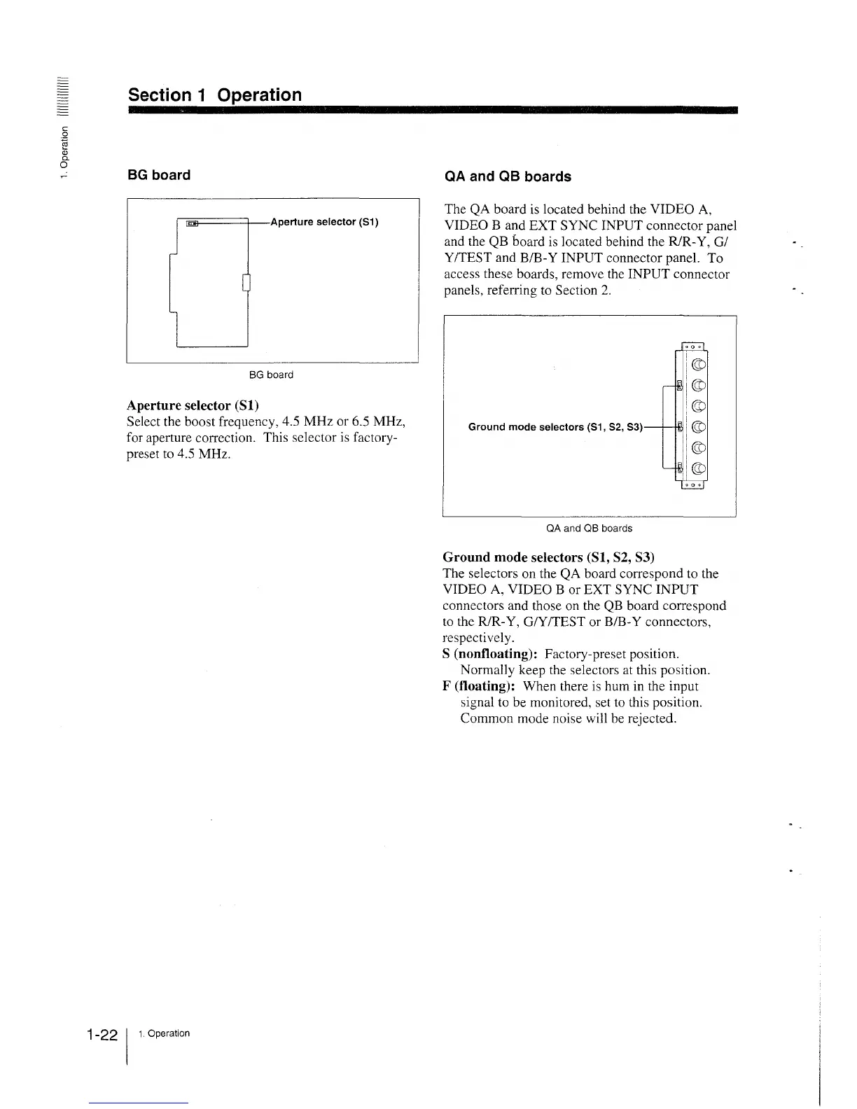
QA and QB boards
The QA board is located behind the VIDEO A,
VIDEO Band EXT SYNC INPUT connector panel
and the QB board is located behind the R/R-Y, GI
Y/TEST and B/B-Y INPUT connector panel. To
access these boards, remove the INPUT connector
panels, referring to Section 2.
QA and QB boards
Ground mode selectors (Sl, S2, S3)
The selectors on the QA board correspond to the
VIDEO A, VIDEO B or EXT SYNC INPUT
connectors and those on the QB board correspond
to the R/R-Y, G/Y/TEST or B/B-Y connectors,
respectively.
S (nonfloating): Factory-preset position.
Normally keep the selectors at this position.
F (floating): When there is hum in the input
signal to be monitored, set to this position.
Common mode noise will be rejected.