3-13-5. Convergence Correction Waveform Generator
(DB BOARD)
This monitor incorporates unique convergence circuit which can
adjust convergence at 15 positions of the picture screen, each 15
potentiometers for horizontal and vertical convergence adjustments
are located on the left side of the drawer corresponding to the
picture screen.
3-13-6. Horizontal Convergence Correction Waveform
Generator
A vertical rate parabola waveform is supplied to the DB board
from the DB board and is inverted and switched to make correction
waveform.
For the left side of the picture screen, the correction waveform is
compounded by adjusting potentiomerters RV16 - RV20 on the
DC board. This waveform is converted to horizontal rate parabola
waveform which level is proportional to the compounded waveform
by H parabola generator (IC6, Q25). This is amplified by transistor
Q26 and clamped at the center position of the horizontal period by
transistor Q28 and IC6. See Figure 26.
Figure 26
For the right side of the picture screen, the correction waveform
is generated by adjusting potentiometers RV26 - RV30 on the DC
board as same as the left side of the picture.
These correction waveforms (left and right side) are switched and
mixed by analog switcher which activates at 1/2H period as seen
in Figure 27.
~
H --i
r,
I I
e, .
L _: ___,, __ _
I
e, r~
_Lo_~
IC9 ICI b I
SW I L_J
Figure 27
As a result, right side adjustments and left side adjustment can be
performed independently" of each other.
For the center of the picture screen, vertical parabola waveform is
compounded to the correction waveform by adjusting potentio-
meters RV21 - 25 on the DC board, and converted to horizontal
pulse. This means amplitude of horizontal pulse is modulated by
vertical parabola. (Q40, Q41) See Figure 24.
3-29
This modulated pulse is mixed with horizontal parabola for left and
right side correction. This mixed waveform is amplified and supplied
to convergence plate in CRT via DCT. Thus horizontal covergence
is corrected. See Figure 28.
modulated byI
V parabola
rH~
Figure 28
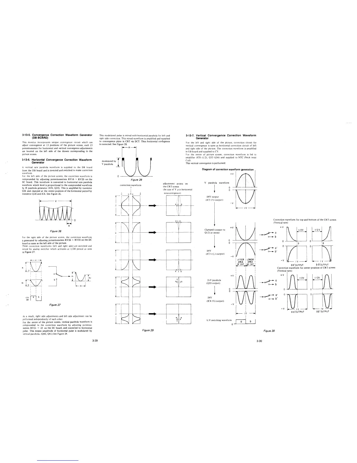
3-13-7. Vertical Convergence Correction Waveform
Generator
For the left and right side of the picture, correction circuit for
vertical convergence is same as horizontal correction circuit of left
and right side of the picture. The correction waveform is amplified
in EB board and supplied to CY.
1:or the center of picture screen, correction waveform is fed to
amplifier (IC8 (1/2), Q33 ()34) and supplied to NTC (Neck twist
Coil).
This vertical convergence is performed.
Diagram of correction waveform generation
+v
correction waveform
adjustment points on
the CRT screen
V parabola
l
waveform
0
0
•
r
r
<
L
r
I
<
L
Figure 29
( In case of Y axis horizontal
misconvcrgence)
R G B
' ,
I,
,,
R G B
G
,,
''
R,:( /1B
,,
,,
R , I B
4 ):,
G', I
INV output
(IC3 (½) output)
Clamped (output to
Ql 2) at center
l
INV
(IC3 (2/
2
) output)
2x V parabola
(Q20 output)
!
INV
(IC4 (½) output)
-v
+v
0
0
-v
+v
0
0
-V
½ V switching waveform
0
IV
I I
I UP PER I LOWEfl I
I AREA I AREA I
1
OF CRT
1
~F CRT
1
,. ~1 '"'
I
I
I
I
I
I
I
IV
a
b
Correction waveform for top and bottom of the CRT screen
(Vertical rate)
~a
0---. b
-~a
0---. b
Figure 30
3-30
+v
l/2V
Q--1.--"""',--~
,a
o--,---~----,
-v
IV
OO'OUTPUT
tt1
,0
o~--....-:---r
IV
b b'OUTPUT
Correction waveform for center position of CRT screen
(Vertical rate)
+v
1 /2V
0
-v
IV-j
IV
a a'OUTPUT
bb' OUTPUT