EasyManua.ls Logo

Sony CDX-F5000 User Manual

Sony CDX-F5000
44 pages
To Next Page IconTo Next Page
Page #1 background imageLoading...
Page #1 background image
1
Ver 1.1 2004. 05
Model Name Using Similar Mechanism CDX-R3000/RW300
CD Drive Mechanism Type MG-611XA-186//K
Optical Pick-up Name KSS1000E
SERVICE MANUAL
US Model
CDX-F5000/FW500
Canadian Model
CDX-F5000
CDX-F5000/FW500
AUDIO POWER SPECIFICATIONS
POWER OUTPUT AND TOTAL HARMONIC DISTORTION
23.2 watts per channel minimum continuous average power into
4 ohms, 4 channels driven from 20 Hz to 20 kHz with no more
than 5% total harmonic distortion.
CD player section
Signal-to-noise ratio 120 dB
Frequency response 10 – 20,000 Hz
Wow and flutter Below measurable limit
Tuner section
FM
Tuning range 87.5 – 107.9 MHz
Antenna terminal External antenna connector
Intermediate frequency 10.7 MHz/450 kHz
Usable sensitivity 9 dBf
Selectivity 75 dB at 400 kHz
Signal-to-noise ratio 67 dB (stereo),
69 dB (mono)
Harmonic distortion at 1 kHz
0.5% (stereo),
0.3% (mono)
Separation 35 dB at 1 kHz
Frequency response 30 – 15,000 Hz
AM
Tuning range 530 – 1,710 kHz
Antenna terminal External antenna connector
Intermediate frequency 10.7 MHz/450 kHz
Sensitivity 30 µV
Power amplifier section
Outputs Speaker outputs
(sure seal connectors)
Speaker impedance 4 – 8 ohms
Maximum power output 52 W × 4 (at 4 ohms)
SPECIFICATIONS
General
Outputs Audio outputs terminal (rear/sub switchable)
Power antenna relay control terminal
Power amplifier control terminal
Inputs Telephone ATT control terminal
Remote controller input terminal
BUS control input terminal
BUS audio input terminal
Antenna input terminal
Tone controls Low: ±10 dB at 60 Hz (XPLOD)
Mid: ±10 dB at 1 kHz (XPLOD)
High: ±10 dB at 10 kHz (XPLOD)
Power requirements 12 V DC car battery
(negative ground)
Dimensions Approx. 178 × 50 × 177 mm
(7 1/8 × 2 × 7 in.) (w/h/d)
Mounting dimensions Approx. 182 × 53 × 161 mm
(7 1/4 × 2 1/8 × 6 3/8 in.) (w/h/d)
Mass Approx. 1.2 kg
(2 lb. 10 oz.)
Supplied accessories Parts for installation and connections (1 set)
Front panel case (1)
Card remote commander RM-X115
Design and specifications are subject to change without
notice.
• The tuner and CD sections have no adjustments.
Sony Corporation
e Vehicle Company
Published by Sony Engineering Corporation
9-961-429-02
2004E04-1
© 2004. 05
FM/AM COMPACT DISC PLAYER

Other manuals for Sony CDX-F5000

Question and Answer IconNeed help?

Do you have a question about the Sony CDX-F5000 and is the answer not in the manual?

Sony CDX-F5000 Specifications

General IconGeneral
Preamp OutputsYes
CD PlaybackYes
MP3 PlaybackYes
USB PortNo
BluetoothNo
Pre-outYes
CD-R/RW PlaybackYes
Display TypeLCD
Detachable FaceplateYes
Channels4
CD TextYes
AAC PlaybackNo
Remote ControlYes
EQYes
Preset EQYes
TunerAM/FM
Aux-InYes

Summary

Service Manual Overview

Audio Power Specifications

Details on power output and total harmonic distortion.

General Specifications

Technical specifications for CD player, tuner, and amplifier sections.

Service Notes and Precautions

Handling Sensitive Components

Guidelines for safely handling optical pick-up and laser diode.

Repair and Testing Procedures

Notes on component replacement and test disc usage.

Critical Safety Warnings

Safety warnings related to repair and adjustments.

Disc Compatibility and Service Information

CD-R/CD-RW Playback Compatibility

Information on playback compatibility for recordable and rewritable CDs.

Service Procedures and Soldering

Procedures for using extension cables and handling unleaded solder.

General Information and Controls

Unit Control Locations

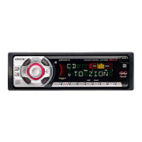
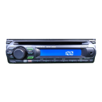
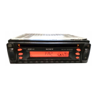
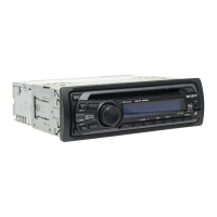
Identification and function of controls on the CDX-F5000/FW500 units.

Unit Connections Overview

Basic connection information for the CDX-F5000/FW500 models.

Remote Commander Details

Description of the card remote commander and its functions.

Electrical Connections (CDX-F5000)

CDX-F5000 Wiring Diagram

Detailed connection diagram for the CDX-F5000 model.

Power and Speaker Connection Notes

Important considerations for power supply, control leads, and speaker connections.

Electrical Connections (CDX-FW500)

CDX-FW500 Wiring Diagram

Detailed connection diagram for the CDX-FW500 model.

Power and Speaker Connection Notes

Important considerations for power supply, control leads, and speaker connections.

SECTION 2 DISASSEMBLY

Disassembly Sequence Overview

Outline of the recommended disassembly steps for the unit.

Initial Panel and Mechanism Removal

Procedures for removing the sub panel and CD mechanism block.

Board and Chassis Component Removal

Steps to remove main board, chassis, and servo board.

Internal Mechanism Component Disassembly

Details on disassembling roller arm, chassis (OP), and related parts.

Critical Component Extraction

Steps for removing optical pick-up, SL motor, and LE motor assemblies.

SECTION 3 DIAGRAMS

IC Pin Descriptions

Detailed pinout information for key ICs on the Servo and Main boards.

Block Diagrams - CD Section

CD Section Block Diagram

Overview of the CD section's signal flow and component interconnections.

Block Diagrams - Main Section

Main Section Block Diagram

Diagram illustrating the main section's signal paths and IC interactions.

Diagrams and Layouts

Display Section Block Diagram

Signal flow and component overview for the display section.

Circuit Board Locations

Visual guide showing the placement of main electronic boards within the unit.

Diagram Notes and Waveforms

Notes for Diagrams and Schematics

Explanations for symbols, lines, and conventions used in diagrams.

Key Waveform Examples

Visual representations of important signal waveforms for troubleshooting.

Printed Wiring Boards - CD Mechanism Section

CD Mechanism Section PWBs

Layouts of the printed wiring boards for the CD mechanism.

Schematic Diagrams - CD Mechanism Section

CD Mechanism Section Schematic

Detailed circuit schematic for the CD mechanism section.

Schematic Diagrams - Main Section (Part 1)

Main Section Schematic (Part 1)

Circuit schematic for the main section, covering initial parts.

Schematic Diagrams - Main Section (Part 2)

Main Section Schematic (Part 2)

Continuation of the main section circuit schematic, covering remaining parts.

Printed Wiring Boards - Main Section

Main Section PWBs

Layouts of the printed wiring boards for the main section.

Relay Section Diagrams

Relay Section PWB Layout

Printed wiring board layout for the relay section.

Relay Section Schematic Diagram

Circuit schematic for the relay section.

Printed Wiring Boards - Display Section

Display Section PWB Layout

Printed wiring board layout for the display section.

Schematic Diagrams - Display Section

Display Section Schematic

Circuit schematic for the display section.

IC Block Diagrams

Servo and Main Board IC Block Diagrams

Simplified block diagrams illustrating the internal functions of key ICs.

SECTION 4 EXPLODED VIEWS

Main Section Exploded View

Visual breakdown of the main section components for identification and replacement.

Exploded Views - Front Panel

Front Panel Section Exploded View

Visual breakdown of the front panel components for identification and replacement.

Exploded Views - CD Mechanism (1)

CD Mechanism Section Exploded View (Part 1)

Visual breakdown of CD mechanism parts for identification and replacement.

Exploded Views - CD Mechanism (2)

CD Mechanism Section Exploded View (Part 2)

Continuation of the CD mechanism exploded view detailing further components.

Exploded Views - CD Mechanism (3)

CD Mechanism Section Exploded View (Part 3)

Third part of the CD mechanism exploded view, showing additional components.

Exploded Views - CD Mechanism (4)

CD Mechanism Section Exploded View (Part 4)

Final part of the CD mechanism exploded view, detailing remaining components.

SECTION 5 ELECTRICAL PARTS LIST

Display Board Components

List of electrical components for the display board, including LEDs and LCD.

Capacitors and Connectors

Listing of various capacitors and connector types used in the unit.

Diodes and ICs

List of diodes and integrated circuits with their part numbers.

Resistors and Switches

Catalog of resistors and switches used in the electrical system.

Electrical Parts List - Transistors and Resistors

Transistors and Resistors

Detailed list of transistors and resistors with their specifications and part numbers.

Electrical Parts List - Capacitors and Diodes

Capacitors and Diodes

Comprehensive list of capacitors and diodes used in the unit.

Electrical Parts List - ICs, Coils, and Transistors

ICs, Coils, and Transistors

List of integrated circuits, coils, and transistors.

Electrical Parts List - Switches and Tuner Components

Switches and Tuner Components

Listing of various switches and tuner-related components.

Electrical Parts List - Sensor Board Components

Sensor Board Components and Ferrite Beads

Parts list for the sensor board, including ferrite beads and transistors.

Miscellaneous and Accessory Information

Accessories and Manuals

List of included accessories, remote commander, and instruction manuals.

Installation and Connection Parts

Components required for installation and connection of the unit.

Related product manuals