– 1 –
Model Name Using Similar Mechanism NEW
CD
CD Mechanism Type KSM-213CCM
Section
Optical Pick-up Name KSS-213C
TC
Model Name Using Similar Mechanism CFD-ZW150/ZW160
Section
Tape Transport Mechanism Type MF-ZW150
SERVICE MANUAL
US Model
Canadian Model
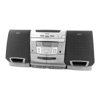
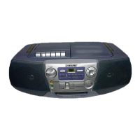
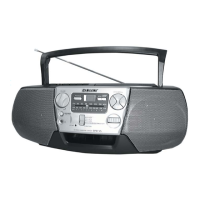
CFD-C1000
CD RADIO CASSETTE-CORDER
SPECIFICATIONS
– Continued on next page –
AUDIO POWER SPECIFICATIONS (US Model)
POWER OUTPUT AND TOTAL
HARMONIC DISTORTION
With 6-ohm loads, both channel driven
from 75 - 15,000 Hz; rated 10 W per
channel-minimum RMS power, with no more
than 1% total harmonic distortion in AC
operation.
Other Specifications
CD player section
System
Compact disc digital audio system
Laser diode properties
Material: GaAlAs
Wave length: 780 nm
Emission duration: Continuous
Laser output: Less than 44.6 µW
(This output is the value measured at a distance of
about 200 mm from the objective lens surface on
the optical pick-up block with 7 mm aperture.)
Spindle speed
200 r/min (rpm) to 500 r/min (rpm) (CLV)
Number of channels
2
Frequency response
20 - 20,000 Hz +1/–2 dB
Wow and flutter
Below measurable limit
Radio section
Frequency range
FM: 87.6 - 108 MHz
AM: 530 - 1,710 kHz
Antenna
FM: Telescopic antenna
AM: Loop antenna
Cassette-corder section
Recording system
4-track 2 channel stereo
Fast winding time
Approx. 120 s (sec.) with Sony cassette C-60
Frequency response
TYPE I (normal): 100 - 10,000 Hz
Ver 1.2 2000. 10