15
CFD-S700
TP
(RF)
TP
(FE)
TP
(TE)
TP
(VREF)
TP
(RF)
TP
(VREF)
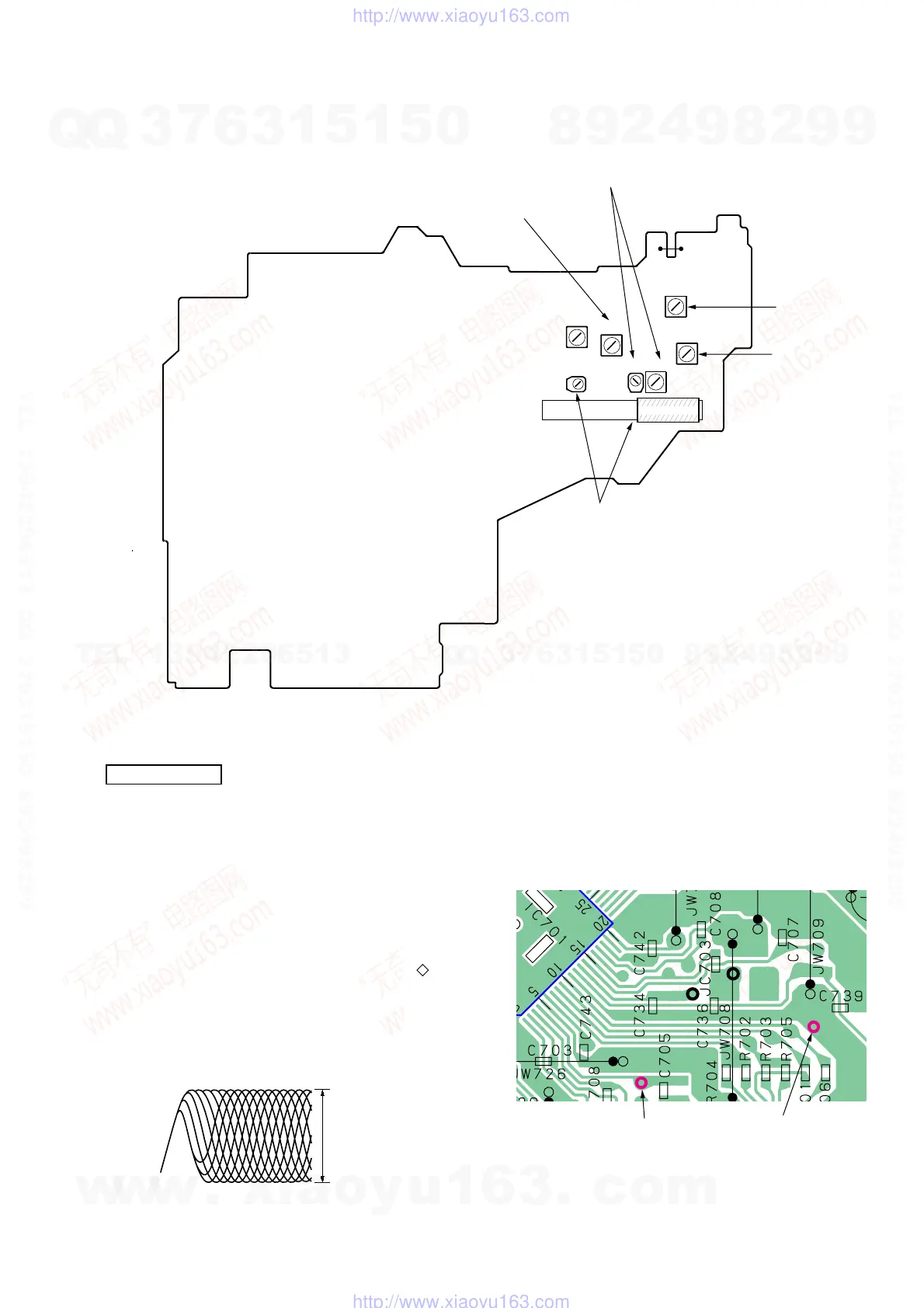
– CD board (conductor side) –
Adjustment Location:
CD SECTION
CD section adjustments are done automatically in this set.
In case of operation check, confirm that focus bias.
Focus Bias Check
1. Connect the oscilloscope between IC701 pin 4 and pin qa (or
TP (RF) and TP (VREF).
2. Insert the disc (YEDS-18). (Part No. : 3-702-101-01)
3. Press the CD N X button.
4. Confirm that the oscilloscope waveform is as shown in the
figure below. (eye pattern)
A good eye pattern means that the diamond shape ( ) in the
center of the waveform can be clearly distinguished.
• RF signal reference waveform (eye pattern)
Test Point:
RF level :
0.85 ± 0.2 Vp-p
VOLT/DIV : 50 mV (10 : 1 probe in use)
TIME/DIV : 500 nS
When observing the eye pattern, set the oscilloscope for AC range
and raise vertical sensitivity.
– MAIN board (component side) –
T2
FM IF
ADJUSTMEN
T2
L2
TP(JW1)
T1
AM IF
ADJUSTMENT
T1
L4
L3
CT1
CT3
L1
L2
FM FREQUENCY
COVERAGE
ADJUSTMENT
CT1, L1
FM TRACKING
ADJUSTMENT
L4
AM
FREQUENCY
COVERAGE
ADJUSTMENT
CT3, L3
AM
TRACKING
ADJUSTMENT
w
w
w
.
x
i
a
o
y
u
1
6
3
.
c
o
m
Q
Q
3
7
6
3
1
5
1
5
0
9
9
2
8
9
4
2
9
8
T
E
L
1
3
9
4
2
2
9
6
5
1
3
9
9
2
8
9
4
2
9
8
0
5
1
5
1
3
6
7
3
Q
Q
TEL 13942296513 QQ 376315150 892498299
TEL 13942296513 QQ 376315150 892498299
http://www.xiaoyu163.com
http://www.xiaoyu163.com