6-1
DVP-K800D
SECTION 6
ELECTRICAL ADJUSTMENT
This section describes procedures and instructions necessary for
adjusting electrical circuits in this set.
Instruments required:
1) NTSC Color monitor TV
2) Oscilloscope 1 or 2 phenomena, band width over 100 MHz,
with delay mode
3) Frequency counter (over 8 digits)
4) Digital voltmeter
5) Standard commander
6) DVD reference disc
HLX-501 (J-6090-071-A) (dual layer)
HLX-503 (J-6090-069-A) (single layer)
7) Extension cable
J-6090-079-A 20P
MB-78 (CN601) ↔FL-106 (CN101)
In making adjustment, refer to 6-4. Adjustment Related
Parts Arrangement.
6-1. POWER SUPPLY CHECK
(MB-78 board)
Mode E-E
Instrument Digital Voltmeter
EVER +5.3V Check
Measurement Point CN001 pin 3
Specification 5.4 ± 0.2V
REG + 3.3V Check
Point CN001 pin 5
Specification 3.3 ± 0.2V
REG +5.2V Check
Point CN001 pins 7, 8
Specification 5.2 ± 0.2V
M +12V Check
Point CN002 pin 2
Specification +12 V
AU +12V Check
Point CN002 pin 7
Specification 12.0 V
AU –12V Check
Point CN002 pin 5
Specification –12 V
Checking method:
1) Confirm that each voltage satisfies the specification.
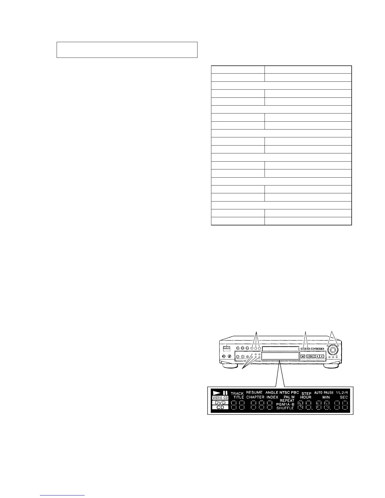
6-2. LEDs, DISPLAY CHECK
Checking method:
1) Press [TITLE], [CLEAR] then [POWER] keys continuously
on the remote commander to enter the test mode in the standby
coudition.
2) Press [5] key on the remote commander.
3) Then following LEDs and display tube are lit.
+1.0
–2.0
+1.0
–2.0
+2.0
–1.0
Turns on
Turns on Turns on
Turns on
• All LEDs are lit