Command List
FCB-EV7520A(GB) D-023-100-11(1)
30
VISCA Communication
Specifications
VISCA packet structure
The basic unit of VISCA communication is called a
packet. The first byte of the packet is called the header
and comprises the sender’s and receiver’s addresses. For
example, the header of the packet sent to the FCB
camera assigned address 1 from the controller (address
0) is hexadecimal 81h. The packet sent to the camera
assigned address 2 is 82h. In the command list, as the
header is 8X, input the address of the camera at X. The
header of the reply packet from the camera assigned
address 1 is 90h. The packet from the camera assigned
address 2 is A0h.
Some of the commands for setting cameras can be sent
to all devices at one time (broadcast). In the case of
broadcast, the header should be hexadecimal 88h.
When the terminator is FFh, it signifies the end of the
packet.
Command and inquiry
Command
Sends operational commands to the FCB camera.
Inquiry
Used for inquiring about the current state of the FCB
camera.
Command Packet Note
Inquiry 8X QQ RR ... FF QQ
1)
= Command/Inquiry,
RR
2)
= category code
1)
QQ = 01 (Command), 09 (Inquiry)
2)
RR = 00 (Interface), 04 (camera 1), 06 (Pan/Tilt), 07 (camera 2)
X = 1 to 7: FCB camera address
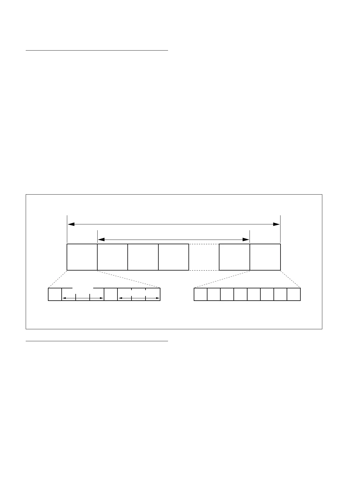
Packet (3 to 16 bytes)
Message (1 to 14 bytes)
Header
Byte 1 Byte 2 Byte 3
Bit 7
(MSB)
Bit 6 Bit 5 Bit 4 Bit 3 Bit 2 Bit 1 Bit 0
(LSB)
1 0
FF
Bit 7
(MSB)
Bit 6 Bit 5 Bit 4 Bit 3 Bit 2 Bit 1 Bit 0
(LSB)
1 1 1 1 1 1 1 1
Sender’s
address
Receiver’s address
Terminator