Specifications
FCB-EV7520A(GB) D-023-100-11(1)
70
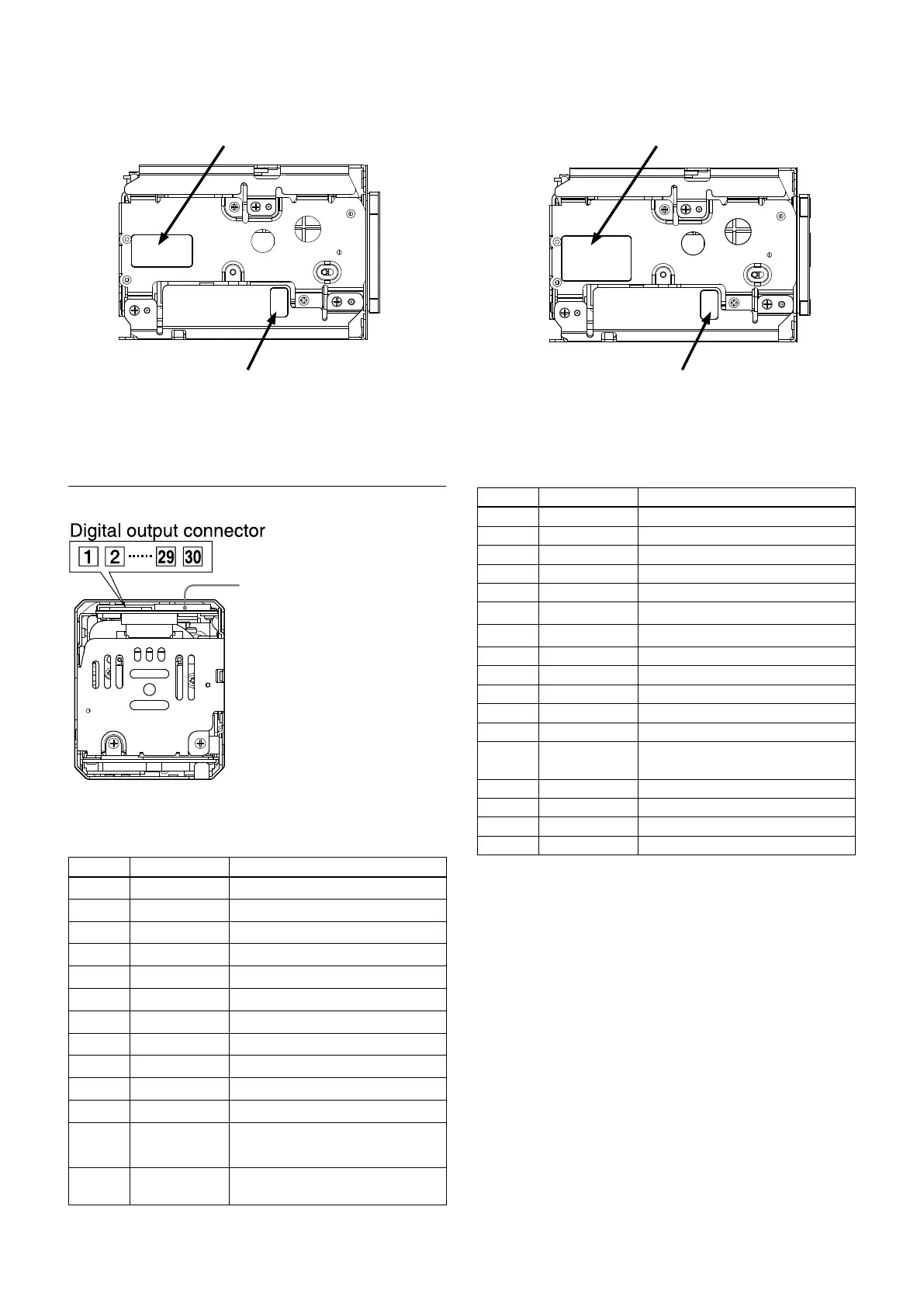
Pin assignment
Maintenance connector
* Do not connect here, this is for
maintenance purpose.
Digital output connector
KEL Co. USL00-30L-C
Pin No. Name Level
1 TXOUT3+
2 TXOUT3−
3 TXCLKOUT+
4 TXCLKOUT−
5 TXOUT2+
6 TXOUT2−
7 TXOUT1+
8 TXOUT1−
9 TXOUT0+
10 TXOUT0−
11 GND
12 TxD
CMOS 5 V (Low: Max 0.1 V,
High: Min 4.4 V)
13 RxD CMOS 5 V (Low: Max 1.0 V,
High: Min 2.3 V)
Label drawings
FCB-EV7520A FCB-CV7520A
Pin No. Name Level
14 DC IN 6 to 12 V DC
15 DC IN 6 to 12 V DC
16 DC IN 6 to 12 V DC
17 DC IN 6 to 12 V DC
18 DC IN 6 to 12 V DC
19 GND
20 GND
21 TXOUT7+ Single out mode: open
22 TXOUT7– Single out mode: open
23 TXOUT6+ Single out mode: open
24 TXOUT6– Single out mode: open
25 NC
26 RESET
Reset: Low (GND),
Normal: Open (1.8V)
27 TXOUT5+ Single out mode: open
28 TXOUT5– Single out mode: open
29 TXOUT4+ Single out mode: open
30 TXOUT4– Single out mode: open
Name plate
Manufacturing control label
Name plate
Manufacturing control label