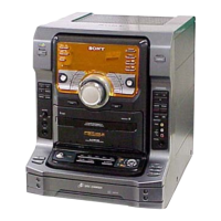
FST-GTK11iP/GTK33iP/RDH-GTK11iP/GTK33iP
58
Pin No. Pin Name I/O Description
57 S-MASTER DATA O Serial data output to the stream processor
58 S-MASTER SHIFT O Serial data transfer clock signal output to the stream processor
59 S-MASTER LATCH O Serial latch pulse signal output to the stream processor
60
S-MASTER
NSP MUTE
O NSP muting on/off control signal output to the stream processor
61 S-MASTER INIT O Reset signal output to the stream processor “L”: reset
62 Vcc - Power supply terminal (+3.3V)
63 NC - Not used
64 Vss - Ground terminal
65 LED_LEVEL_IN I LED level synchronization signal input termianl
66 AUDIO LEVEL DET I Audio level detection signal input termianl for auto standby function
67 S-MASTER DCP I Speaker DC detection signal input terminal “L”: speaker DC is detected
68 USB MCHNG I Music change signal input from the audio decoder
69 AC_DET I AC cut detection signal input terminal “L”: AC cut
70, 71 KEY_1, KEY_2 I Panel key input terminal (A/D input)
72 VOL_JOG I Jog dial pulse input terminal for VOLUME dial
73 IP_DETECT I iPod/iPhone detection signal input terminal
74
KEY_WAKE_UP_
POWER
I Key wake-up signal input terminal
75 STBY LED O LED drive signal output terminal for on/standby indicator “H”: LED on
76 USB IRPTO I Interrupt request signal input from the audio decoder
77 USB SDA I/O Two-way data bus with the audio decoder
78 USB SCL O Serial data transfer clock signal output to the audio decoder
79 USB BUSY I Busy signal input from the audio decoder
80 USB RESET O Reset signal output to the audio decoder
81 IP_ON O Power on/off control signal output terminal for iPod/iPhone section “H”: power on
82 USB_ON O Power on/off control signal output terminal for USB section “H”: power on
83 USB_IP_OCP I VBUS over current detection signal input terminal
84 USB_IPOD SEL O Audio selection signal output terminal “L”: iPod/iPhone, “H”: USB
85 SUB-ON O Main power on/off control signal output terminal “H”: main power on (GTK11iP only)
86 P-ON O Power on/off control signal output terminal for regulator section “H”: power on
87 BYPASS - Not used
88 POWER PROTECT I Protect signal input from regulator section
89 VART DET - Not used
90 PVDD_ON O Main power on/off control signal output terminal “H”: main power on (GTK33iP only)
91 to 93 NC - Not used
94 VACS I VACS reference signal input terminal
95 MODEL-IN I Model setting terminal
96 AVss - Ground terminal
97 SPEC-IN I Destination setting terminal
98 VREF I Reference voltage (+3.3V) input terminal
99 AVcc - Power supply terminal (+3.3V)
100 DP INH O Blank indicate control signal output to the liquid crystal display driver "H": display on

 Loading...