26
HCD-AZ2D/AZ5D
3. Mode: Playback
4. After the adjustments, apply suitable locking compound to
the pats adjusted.
Adjustment Location: Playback Head (DECK-A)
Record/Playback/Erase Head (DECK-B)
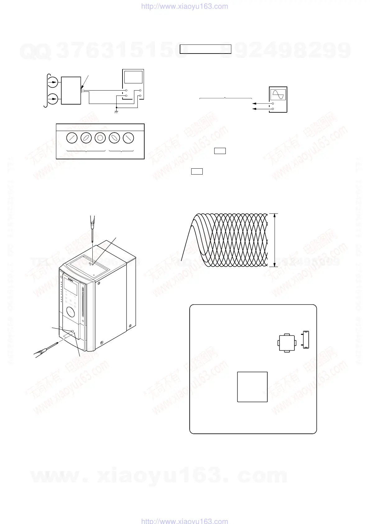
RFMON LEVEL CHECK
Procedure :
1. Connect the oscilloscope to CN105 pin 6 (RFMON) and
CN105 pin 3 (GND) on the DMB10 board.
2. Press the `/1 button to turn the power on.
3. Insert the test disc (DVD: TDV-520CSO (Part No. J-2501-
236-A), CD: LUV-P01 (Part No. 4-999-032-01) and touch the
Y sensor to playback.
4. Confirm that oscilloscope waveform is as shown in the
figure below. (eye pattern)
A good eye pattern means that the diamond shape (◊) in the
center of the waveform can be clearly distinguished.
Checking Location:
DVD SECTION
set
test tape
P-4-A063
(6.3 kHz, –10 dB)
oscilloscope
V
H
waveform of oscilloscope
in phase 45
°
90
°
135
°
180
°
good
wrong
MAIN board
VIDEO/SAT OUT
jack (J101)
reverse
forward
forward
+
–
DMB10 board
CN105 pin
6
(RFMON)
CN105 pin
3
(GND)
oscilloscop
(DC range)
VOLT/DIV: 200 m
TIME/DIV: 500 ns
level:
0.8
±
0.2 Vp-p (DVD)
0.8
±
0.2 Vp-p (CD)
IC102
– DMB10 BOARD (Side A) –
IC201
CN105
1
6
w
w
w
.
x
i
a
o
y
u
1
6
3
.
c
o
m
Q
Q
3
7
6
3
1
5
1
5
0
9
9
2
8
9
4
2
9
8
T
E
L
1
3
9
4
2
2
9
6
5
1
3
9
9
2
8
9
4
2
9
8
0
5
1
5
1
3
6
7
3
Q
Q
TEL 13942296513 QQ 376315150 892498299
TEL 13942296513 QQ 376315150 892498299
http://www.xiaoyu163.com
http://www.xiaoyu163.com