SERVICE MANUAL
Sony Corporation
Published by Sony EMCS (Malaysia) PG Tec
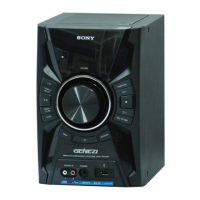
HCD-EC599
SPECIFICATIONS
COMPACT DISC RECEIVER
9-890-594-01
2012B08-1
©
2012.02
E Model
Ver. 1.0 2012.02
• HCD-EC599 is the amplifi er, USB, CD player
and tuner section in MHC-EC599.
Model Name Using Similar Mechanism HCD-EX600
Base Unit Name BU-D1BD76
Optical Pick-up Block Name DA11MMVGP
• MPEG Layer-3 audio coding technology and patents licensed from Fraunhofer IIS and Thomson.
• Windows Media is either a registered trademark or trademark of Microsoft Corporation in the
United States and/or other countries.
• This product is protected by certain intellectual property rights of Microsoft Corporation. Use or
distribution of such technology outside of this product is prohibited without a license from Micro-
soft or an authorized Microsoft subsidiary.
Amplifi er section
Argentina model
The following are measured at AC 220 V,
50/60 Hz
Power output (rated):
30 W + 30 W (at 6 ohms, 1 kHz,
1% THD)
Other models
The following are measured at
Mexican model:
AC 127 V, 60 Hz
Other models:
AC 120 V, 220 V, 240 V, 50/60 Hz
Power output (rated):
30 W + 30 W (at 6 ohms, 1 kHz,
1% THD)
RMS output power (reference):
60 W + 60 W (per channel at 6 ohms,
1 kHz)
Inputs
DVD/PC IN L/R
Voltage 1.5 V, impedance 47 kilohms
(USB) port: Type A
Outputs
PHONES (stereo mini jack)
Accepts headphones with an
impedance of 8 ohms or more
USB section
Supported bit rate
MP3 (MPEG 1 Audio Layer-3):
32 kbps – 320 kbps, VBR
WMA: 48 kbps – 192 kbps
AAC: 48 kbps – 320 kbps
Sampling frequencies
MP3 (MPEG 1 Audio Layer-3):
32/44.1/48 kHz
WMA: 44.1 kHz
AAC: 44.1 kHz
Supported USB device
Mass Storage Class
Maximum current
500 mA
Disc player section
System
Compact disc and digital audio system
Laser Diode Properties
Emission Duration: Continuous
Laser Output*: Less than 44.6 μW
* This output is the value measurement
at a distance of 200 mm from the
objective lens surface on the Optical
Pick-up Block with 7 mm aperture.
Frequency response
20 Hz – 20 kHz
Signal-to-noise ratio
More than 90 dB
Dynamic range
More than 88 dB
Tuner section
FM stereo, FM/AM superheterodyne tuner
Antenna
FM lead antenna
AM loop antenna
FM tuner section
Tuning range
87.5 MHz – 108.0 MHz (50 kHz step)
AM tuner section
Tuning range
530 kHz – 1,710 kHz (10 kHz step)
531 kHz – 1,710 kHz (9 kHz step)
Standby power consumption: 0.5 W
Design and specifi cations are subject to
change without notice.
• “WALKMAN” and “WALKMAN” logo are registered trademarks of Sony Corporation.
• MPEG Layer-3 audio coding technology and patents licensed from Fraunhofer IIS and Thomson.
• Windows Media is either a registered trademark or trademark of Microsoft Corporation in the
United States and/or other countries.
• This product contains technology subject to certain intellectual property rights of Microsoft.
Use or distribution of this technology outside of this product is prohibited without the appropriate
license(s) from Microsoft.