SERVICE MANUAL
Sony Corporation
Audio Business Group
Published by Sony Techno Create Corporation
section
HCD-EC78
European and Russian models:
Power output (rated):
Low channel
55 W + 55 W (at 8 Ω, 1 kHz, 1% THD)
High channel
55 W + 55 W (at 8 Ω, 8 kHz, 1% THD)
RMS output power (reference):
Low channel
75 W + 75 W (per channel at 8 Ω, 1 kHz, 10% THD)
High channel
75 W + 75 W (per channel at 8 Ω, 8 kHz, 10% THD)
Other models:
Power output (rated):
Low channel
50 W + 50 W (at 8 Ω, 1 kHz, 1% THD)
High channel
50 W + 50 W (at 8 Ω, 8 kHz, 1% THD)
RMS output power (reference):
Low channel
70 W + 70 W (per channel at 8 Ω, 1 kHz, 10% THD)
High channel
70 W + 70 W (per channel at 8 Ω, 8 kHz, 10% THD)
HCD-EC68
European and Russian models (except for the UK model):
Power output (rated):
50 W + 50 W (at 6 Ω, 1 kHz, 1% THD)
RMS output power (reference):
70 W + 70 W (per channel at 6 Ω, 1 kHz, 10% THD)
Power output (rated):
55 W + 55 W (at 6 Ω, 1 kHz, 1% THD)
RMS output power (reference):
75 W + 75 W (per channel at 6 Ω, 1 kHz, 10% THD)
Other models:
Power output (rated):
50 W + 50 W (at 6 Ω, 1 kHz, 1% THD)
RMS output power (reference):
70 W + 70 W (per channel at 6 Ω, 1 kHz, 10% THD)
Inputs
AUDIO IN (stereo mini jack): Sensitivity 800 mV, impedance
22 kilohms
Outputs
PHONES (stereo mini jack): Accepts headphones with an
impedance of 8 Ω or more
SPEAKER: impedance
HCD-EC78: 8 Ω
HCD-EC68: 6 Ω
CD player section
System: Compact disc and digital audio system
Laser: Semiconductor laser (λ=770 – 810 nm)
Emission duration: continuous
Frequency response: 20 Hz – 20 kHz
Signal-to-noise ratio: More than 90 dB
Dynamic range: More than 88 dB
Tape deck section (except for the UK model)
Recording system: 4-track 2-channel, stereo
Tuner section
FM stereo, FM/AM superheterodyne tuner
Antenna:
FM lead antenna
AM loop antenna
FM tuner section:
Tuning range:
87.5 – 108.0 MHz (50 kHz step)
Intermediate frequency: 10.7 MHz
AM tuner section:
Tuning range
Australian, Pan-American models:
530 – 1,710 kHz (with 10 kHz tuning interval)
531 – 1,710 kHz (with 9 kHz tuning interval)
European and Russian models:
531 – 1,602 kHz (with 9 kHz tuning interval)
Other models:
530 – 1,610 kHz (with 10 kHz tuning interval)
531 – 1,602 kHz (with 9 kHz tuning interval)
Intermediate frequency: 450 kHz
HCD-EC68/EC78
SPECIFICATIONS
EXCEPT HCD-EC68: UK MODEL
COMPACT DISC DECK RECEIVER
HCD-EC68: UK MODEL
COMPACT DISC RECEIVER
9-889-007-01
2008B05-1
©
2008.02
AEP Model
E Model
HCD-EC68/EC78
UK Model
Australian Model
HCD-EC68
Ver. 1.0 2008.02
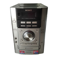
• HCD-EC68 is the amplifi er, CD player, tape
deck (except UK model) and tuner section in
MHC-EC68.
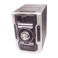
• HCD-EC78 is the amplifi er, CD player, tape
deck and tuner section in MHC-EC78.
Photo : HCD-EC78
CD
Section
Model Name Using Similar Mechanism
NEW
Mechanism Type
CDM88A-K6BD90-WOD
Optical Pick-up Block Name
KSM-213DCP
Tape deck
Section
(EXCEPT EC68: UK)
Model Name Using Similar Mechanism
HCD-EC77
Tape Transport Mechanism Type
TCM-J1 or
CS-21SC-900TP
– Continued on next page –
w
w
w
.
x
i
a
o
y
u
1
6
3
.
c
o
m
Q
Q
3
7
6
3
1
5
1
5
0
9
9
2
8
9
4
2
9
8
T
E
L
1
3
9
4
2
2
9
6
5
1
3
9
9
2
8
9
4
2
9
8
0
5
1
5
1
3
6
7
3
Q
Q
TEL 13942296513 QQ 376315150 892498299
TEL 13942296513 QQ 376315150 892498299
http://www.xiaoyu163.com
http://www.xiaoyu163.com