HCD-EH25/EH26
9
SECTION 5
MECHANICAL ADJUSTMENTS
Precaution
1. Clean the following parts with a denatured-alcohol-moistened
swab:
record/playback head pinch roller
erase head rubber belts
capstan idlers
2. Demagnetize the record/playback head with a head demag-
netizer. (Do not bring the head magnetizer close to the erase
head.)
3. Do not use a magnetized screwdriver for the adjustments.
4. After the adjustments, appiy suitable locking compound to the
parts adjusted.
5. The adjustments should be performed with the rated power
supply voltage unless otherwise noted.
Torque Measurement
SECTION 6
ELECTRICAL ADJUSTMENTS
1. Demagnetize the record/playback head with a head
demagnetizer.
2. Do not use a magnetized screwdriver for the adjustments.
TEST TAPE
Tape Signal Used for
P-4-A063 6.3 kHz, –10 dB Azimuth Adjustment
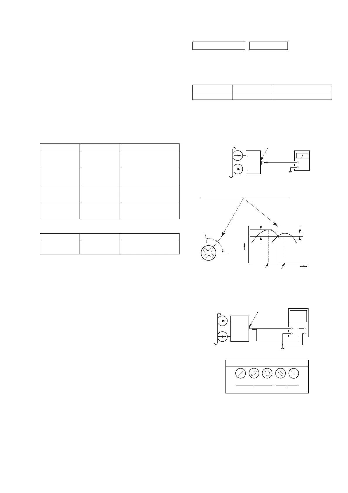
RECORD/PLAYBACK HEAD AZIMUTH ADJUSTMENT
Procedure:
1. Mode: Playback
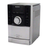
2. Turn the adjustment screw and check output peaks. If the peaks
do not match for L-CH and R-CH, turn the adjustment screw
so that outputs match within 1dB of peak.
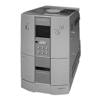
3. Mode: Playback
4. Confi rm that oscilloscope waveform is clear and check RF sig-
nal level is correct or not.
DECK SECTION 0 dB = 0.775
set
MAIN board
PHONES jack
(J102)
+
–
level meter
test tape
P-4-A063
(6.3 kHz, –10 dB)
Screw
position
L-CH
peak
within
1 dB
Output
level
L-CH
peak
R-CH
peak
within
1 dB
Screw
position
R-CH
peak
set
test tape
P-4-A063
(6.3 kHz, –10 dB)
oscilloscope
V
H
waveform of oscilloscope
in phase 45° 90° 135° 180°
good
wrong
MAIN board
PHONES jack
(J102)
Mode Torque meter Meter reading
FWD CQ-102AS
2.0 – 8.0 mN • m
(20 – 80 g • cm)
(0.28 – 1.12 oz • inch)
FWD
Back Tension
CQ-102C
0.15 – 0.6 mN • m
(1.5 – 6.0 g • cm)
(0.021 – 0.083 oz • inch)
FF CQ-201AS
5.0 – 17.7 mN • m
(50 – 177 g • cm)
(0.7 – 2.48 oz • inch)
REW CQ-201B
5.0 – 17.7 mN • m
(50 – 177 g • cm)
(0.7 – 2.48 oz • inch)
Mode Torque meter Meter reading
FWD CQ-403A
more than 80 g
(more than 2.82 oz)
Tape Tension Measurement