16
HCD-GP5
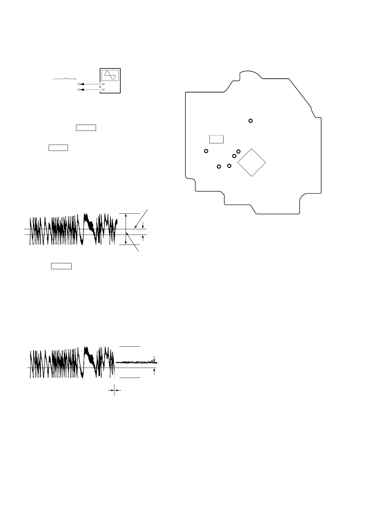
E-F Balance Check
Connection:
Procedure:
1. Connect an oscilloscpe to test point TP (TE) and TP (DVC) on
the CD board.
2. AC is put in pushing CD u button.
3. FL tube carries out all lights and goes into CD test mode.
4. Put the disc (YEDS-18) in to playback the number five track.
5. Press the CD u button. (The tracking servo and the sledding
servo are turned OFF)
6. Check the level B of the oscilliscope's waveform and the A
(DC voltage) of the center of the Traverse waveform.
Confirm the following :
A/B x 100 = less than ± 22%
Traverse Waveform
7. Press the CD u button. (The tracking servo and sledding
servo are turned ON)
Confirm the C (DC voltage) is almost equal to the A (DC
voltage) is step 4.
8. To exit from this mode, turn the power off.
Notes: •Always move the optical pick-up to most inside track when
exiting from this mode. Otherwise, a disc will not be unloaded.
• Do not run the sled motor excessively, otherwise the gear can
be chipped.
Traverse Waveform
Checking Location: CD board (Conductor side)
+
–
CD board
TP (TE)
TP (DVC)
oscilloscope
0V
B
level: 1.15
±
0.5 Vp-p
Center of
the waveform
A (DC
voltage)
0V
Tracking servo
Sled servo
ON
C (DC
voltage)
Tracking servo
Sled servo
OFF
Checking Location:
– CD BOARD (Conductor Side) –
TP (VC)
TP (FE)
TP (TE)
TP
(RFDC)
TP
(DVC)
TP
(RFAC)
IC103
IC101