– 80 –
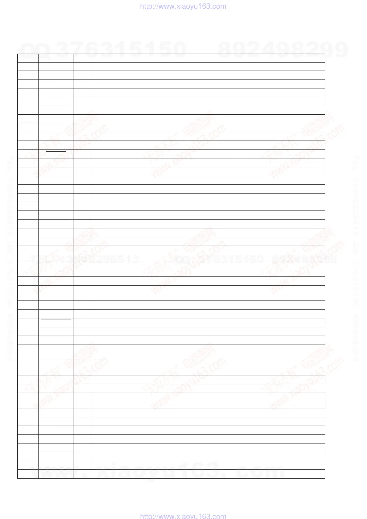
• MAIN BOARD (1/3) IC601 µPD78078GF-062-3BA (MASTER CONTROL)
Pin No. Pin Name I/O Function
1 to 3 VER I Destination setting terminal
4 VER I Destination setting terminal Not used (open)
5 to 7 (NC) — Not used
8 (NC) — Not used (open)
9 IC — Connecting to ground
10 X2 O Main system clock output terminal (5 MHz)
11 X1 I Main system clock input terminal (5 MHz)
12 VDD — Power supply terminal (+5V)
13 XT2 O Sub system clock output terminal (32 kHz)
14 XT1 I Sub system clock input terminal (32 kHz)
15 RESET I System reset signal input from the reset signal generator (IC602)
16 AU-BUS IN I AU-BUS signal input terminal
17
AU-BUS OUT
O AU-BUS signal output terminal
18 ENC/A I Encorder volume signal A input from the master volume (S901)
19 ENC/B I Encoder volume signal B input from the master volume (S901)
20 RDS/CLK I RDS clock signal input from the RDS demodulator (IC1500)
21 RDS/DATA I RDS data signal input from the RDS demodulator (IC1500)
22 SCOR (BD) I Sub-code sync S0, S1 detect signal input from the digital signal processor (IC103)
23 AVDD — Power supply terminal (+5V) (for A/D converter)
24 AVREF0 — Reference voltage input terminal (+5V) (for A/D converter)
25 KEY0 I Key input terminal (A/D input) POWER key (S902) input
26 KEY1 I
Key input terminal (A/D input) p (CD), ^ (CD), § (CD), p (MD), ^ (MD), § (MD) keys
(S903 to S908) input
27 KEY2 I
Key input terminal (A/D input) FUNCTION, ) + +, TUNER/BAND, = 0 –, r REC,
CD-MD SYNC, REPEAT STEREO/MONO, PLAY MODE TUNING MODE (S909 to S916) input
28 to 30 (NC) — Not used
31 O Master-busy signal output to the MD system control (IC316)
32 MD-POWER O MD power on/off signal output to the MD power regulator (IC570)
33 AVSS — Ground terminal (for A/D converter)
34 POWER ON I System power on signal input terminal
35
MD OEM/REST
O MD reset signal output terminal
36 AVREF1 I Reference voltage input terminal (+5V) (for A/D converter)
37 I MD control data signal input from the MD system control (IC316)
38 O MD control data signal output to the MD system control (IC316)
39 MD-CLK O MD control data clock signal output to the MD system control (IC316)
40 VSS — Ground terminal
41 I Mecha-busy signal input from the MD system control (IC316)
42
FL/DRIV DATA
O Display data signal output to the fluorescent indicator drive (IC901)
43
FL/DRIV CLOCK
O Display data clock signal output to the fluorescent indicator drive (IC901)
44 FL/DRIV CS O Display clear signal output to the fluorescent indicator drive (IC901) “L”: data output
45
FL/DRIVE RESET
O Display reset signal output to the fluorescent indicator drive (IC901) “L”: reset
46 BD SUBQ I Sub-code Q data signal input from the CXD2507AQ (IC103)
47 (NC) — Not used (open)
48 BD SQCLK O Sub-code Q data reading clock signal output to the CXD2507AQ (IC103)
49 BD CLOCK O Serial data clock signal output to the CXD2507AQ (IC103)
RTS (TO MD. CTS)
MASTER BUSY
RXD (TO MD. TXD)
RXD
TXD (TO MD. RXD)
TXD
CTS (TO MD. RTS)
MECHA BUSY
w
w
w
.
x
i
a
o
y
u
1
6
3
.
c
o
m
Q
Q
3
7
6
3
1
5
1
5
0
9
9
2
8
9
4
2
9
8
T
E
L
1
3
9
4
2
2
9
6
5
1
3
9
9
2
8
9
4
2
9
8
0
5
1
5
1
3
6
7
3
Q
Q
TEL 13942296513 QQ 376315150 892498299
TEL 13942296513 QQ 376315150 892498299
http://www.xiaoyu163.com
http://www.xiaoyu163.com