HCD-RV222D/RV222DL/RV333D/RV333DL/RV555D
6
SECTION 1
SERVICING NOTES
Notes on Disconnecting Between the OP Section (DVBU101) and the DMB19 Board
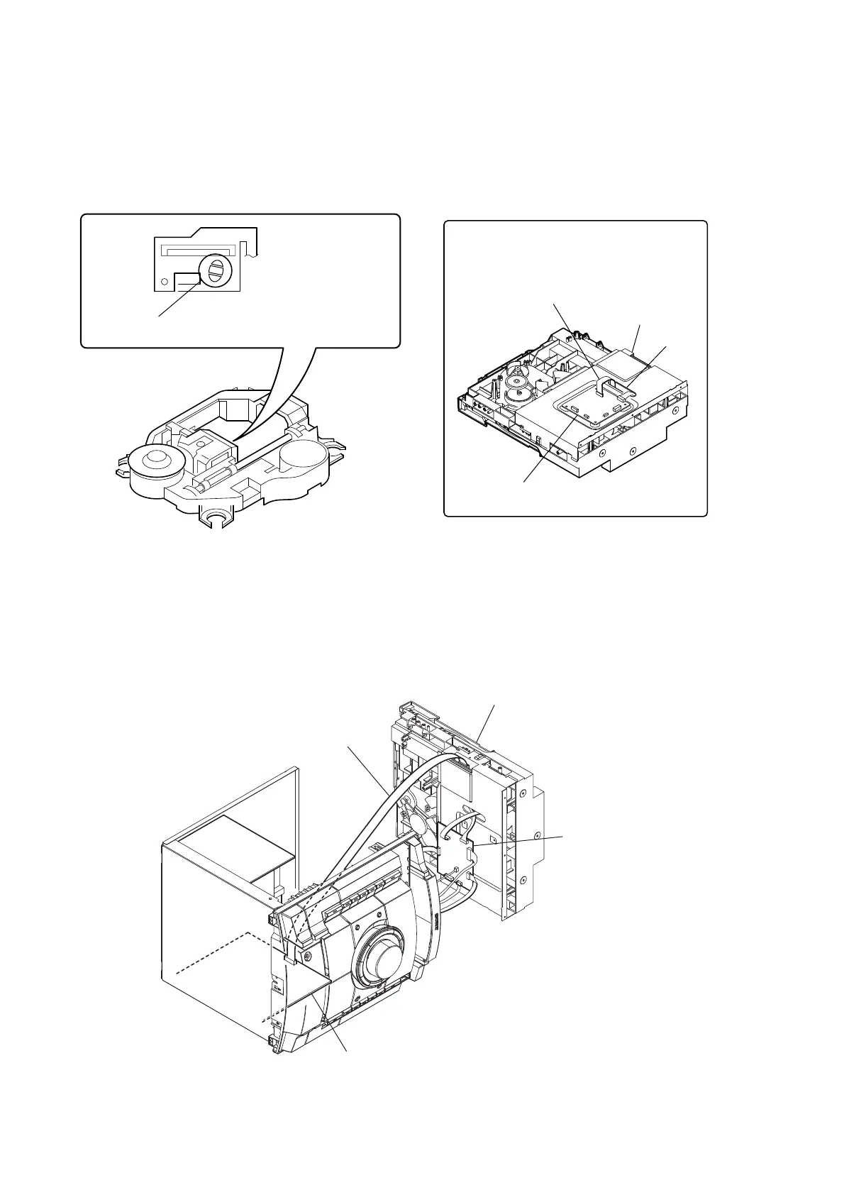
Note: When disconnecting between the OP section (DVBU101) and the DMB19 board, be sure to make a solder bridge for electrostatic prevention as il-
lustrated in the fi gure (before disconnection).
On the contrary, when installing the OP section, never remove the solder bride until the OP section and the DMB19 board are connected.
Be sure to remove the solder bridge after the OP section and the DMB19 board have been connected.
Service Position for the DVD Mechanism Deck Section
Refer to the fi gure given below when disassembling the DVD mechanism deck section.
Use the extension cable J-2501-077-A (1.25mm/13P/300L) as illustrated below.
Perform solder bridging to prevent damage by electrostatic
discharge when handling the BU as a single unit.
DMB19 board
flat cable
sub chassis
hole
Lead the flat cable through the hole in the
sub chassis and connect it to the connector
CN101 on the DMB19 board.
J-2501-077-A
DMB19 board
MAIN board
DVD mechanism deck section
 Loading...