7
HCD-S400
SECTION 3
DISASSEMBLY
Note: Follow the disassembly procedure in the numerical order given.
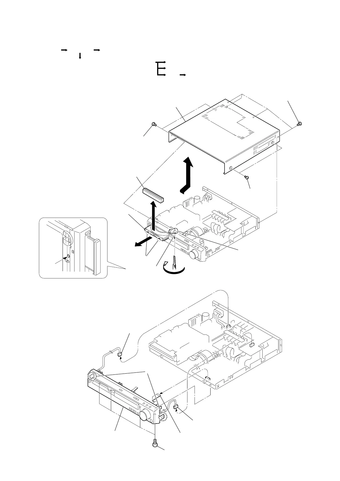
3-1. CASE (TOP), DVD LID, LID WINDOW SUB ASSEMBLY
3-2. FRONT PANEL SECTION
2
Two case screws
1
Two case
screws
Cam
Hole of chassis
5
Turn the cam in the direction of the arrow.
7
Two claws
8
DVD lid,
Lid window sub assembly
6
Pull-out the disc tray.
4
Case (Top)
3
Four screws
(+BVTP 3
×
8
1
Connector (CN309)
3
Connector (CN902)
2
Flexible flat cable (15 core)
(CN005)
5
Two claws
4
Four screws
(+BVTP 3
×
8)
6
Front panel section
RF-240 board
Tray Optical pick-up (KHM-240 AAA)
Front panel sectionCase (Top)Set
Loading board, Motor (LD) assy (M901)DVD mechanism deck (CDM55C-DVBU8)
• The equipment can be removed using the following procedure.