2
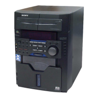
HCD-VM330AV
TABLE OF CONTENTS
1. SERVICING NOTE.................................................. 4
2. GENERAL ................................................................... 5
3. DISASSEMBLY
3-1. Disassembly Flow ........................................................... 7
3-2. Upper Cover .................................................................... 8
3-3. Front Block Assy............................................................. 8
3-4. VIDEO Board.................................................................. 9
3-5. MAIN Board ................................................................... 9
3-6. Back Panel, DC Fan (M391)........................................... 10
3-7. MAIN AMP Board, POWER Board,
VOL SEL Board .............................................................. 10
3-8. Middle (F) Assy, Bracket (Middle-R),
Power Bracket ................................................................. 11
3-9. CD Mechanism Deck (CDM64-30ABD61A) ................ 11
3-10. Base Unit (BU-30ABD61A)........................................... 12
3-11. BU Holder Assy .............................................................. 12
3-12. Cassette Lid Assy (A)/(B) ............................................... 13
3-13. Mech Deck (TAPE) ......................................................... 13
4. TEST MODE.............................................................. 14
5. MECHANICAL ADJUSTMENTS ....................... 15
6. ELECTRICAL ADJUSTMENTS
Deck Section ............................................................................. 15
CD Section ................................................................................ 17
Video Section ............................................................................ 18
Sensor Section........................................................................... 19
7. DIAGRAMS
7-1. Block Diagram – CD SERVO Section – ........................ 21
7-2. Block Diagram – AUDIO/VIDEO Section – ................ 22
7-3. Block Diagram – TUNER/TAPE DECK Section – ...... 23
7-4. Block Diagram – SURROUND Section –...................... 24
7-5. Block Diagram – AMP Section – ................................... 25
7-6. Block Diagram
– DISPLAY/POWER SUPPLY Section – ...................... 26
7-7. Note for Printed Wiring Boards and
Schematic Diagrams ....................................................... 27
7-8. Printed Wiring Board – BD Section – ............................ 28
7-9. Schematic Diagram – BD Section – ............................... 29
7-10. Printed Wiring Board – AUDIO/VIDEO Section – ....... 30
7-11. Schematic Diagram
– AUDIO/VIDEO Section (1/3) – .................................. 31
7-12. Schematic Diagram
– AUDIO/VIDEO Section (2/3) – .................................. 32
7-13. Schematic Diagram
– AUDIO/VIDEO Section (3/3) – .................................. 33
7-14. Printed Wiring Boards
– CD MOTOR/SENSOR Section – ................................ 34
7-15. Schematic Diagram
– CD MOTOR/SENSOR Section – ................................ 35
7-16. Printed Wiring Board – TC Section –............................. 36
7-17. Schematic Diagram – TC Section – ............................... 37
7-18. Schematic Diagram – MAIN Section (1/4) – ................. 38
7-19. Schematic Diagram – MAIN Section (2/4) – ................. 39
7-20. Schematic Diagram – MAIN Section (3/4) – ................. 40
7-21. Schematic Diagram – MAIN Section (4/4) – ................. 41
7-22. Printed Wiring Board – MAIN Section – ....................... 42
7-23. Printed Wiring Boards – AMP Section –........................ 44
7-24. Schematic Diagram – AMP Section – ............................ 45
7-25. Printed Wiring Boards – DISPLAY Section – ............... 46
7-26. Schematic Diagram – DISPLAY Section – .................... 47
7-27. Printed Wiring Board – CONTROL Section – ............... 48
7-28. Schematic Diagram – CONTROL Section –.................. 49
7-29. Printed Wiring Boards – POWER Section – .................. 50
7-30. Schematic Diagram – POWER Section – ...................... 51
7-31. IC Pin Function Description ........................................... 55
8. EXPLODED VIEWS
8-1. General Section ............................................................... 67
8-2. Front Panel Section ......................................................... 68
8-3. Chassis Section ............................................................... 69
8-4. Mechanism Deck Section (CDM64-30ABD61A) ......... 70
8-5. Base Unit Section (BU-30ABD61A) ............................. 71
9. ELECTRICAL PARTS LIST ............................... 72
Tuner section
FM stereo, FM/AM superheterodyne tuner
FM tuner section
Tuning range 87.5 – 108.0 MHz
Antenna FM lead antenna
Antenna terminals 75 ohms unbalanced
Intermediate frequency 10.7 MHz
AM tuner section
Tuning range 530 – 1,710 kHz
(with the interval set at
10 kHz)
531 – 1,602 kHz
(with the interval set at
9 kHz)
Antenna AM loop antenna
Antenna terminals External antenna terminal
Intermediate frequency 450 kHz
General
Power requirements 110 – 120 V or 220 –
240 V AC, 50/60 Hz
Adjustable with voltage
selector
Power consumption 200 watts
Dimensions (w/h/d) incl. projecting parts and controls
Approx. 280 × 383 × 480
mm
Mass: Approx. 12.1 kg
Design and specifications are subject to change
without notice.
w
w
w
.
x
i
a
o
y
u
1
6
3
.
c
o
m
Q
Q
3
7
6
3
1
5
1
5
0
9
9
2
8
9
4
2
9
8
T
E
L
1
3
9
4
2
2
9
6
5
1
3
9
9
2
8
9
4
2
9
8
0
5
1
5
1
3
6
7
3
Q
Q
TEL 13942296513 QQ 376315150 892498299
TEL 13942296513 QQ 376315150 892498299
http://www.xiaoyu163.com
http://www.xiaoyu163.com