15
Locations and Functions of Parts
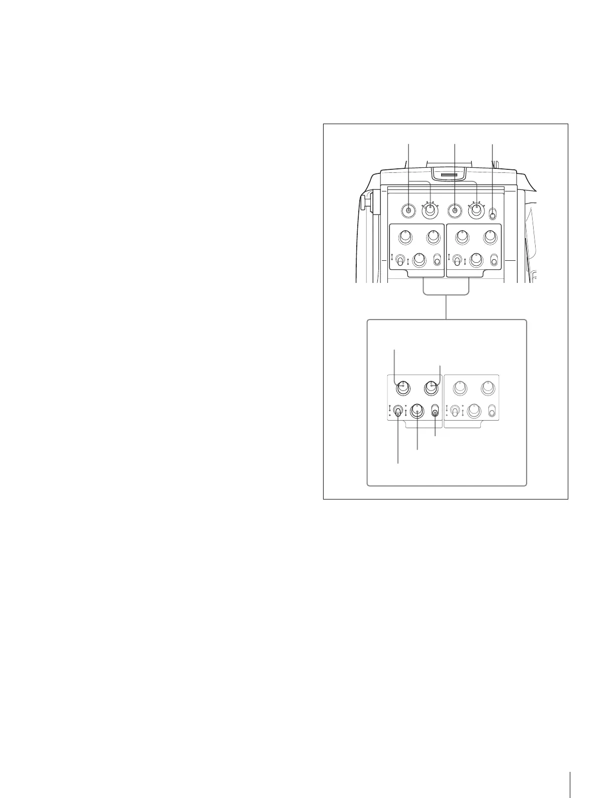
c Tally lamp and switch
ON: The tally lamp lights when a tally signal is input to the
connected camera control unit or a call signal is
generated in response to pressing of a CALL button.
OFF: The tally lamp is prevented from lighting.
d CCU (Camera Control Unit) connector (optical/
electrical multi-connector) (HDC2500/2400)
Connect a camera control unit using an optical electro-
composite cable.
d HDFX (HD Triax CCU) connector (Triax connector)
(HDC2550)
Connect the HDFX100 HD Triax CCU Adaptor using a Triax
cable. A camera control unit can be connected via the
HDFX100.
e SDI 1 (serial digital interface 1) connector (BNC-type)
(HDC2500/2400)
For 3G-SDI, HD-SDI or HD PROMPTER signal output.
f SDI 2 (serial digital interface 2) connector (BNC-type)
(HDC2500/2400)
For HD-SDI signal output or HD TRUNK signal input. During
stand-alone operation, also used for inputting an HD-SDI
return signal. When RET (return) is set to 1, this is displayed
in the viewfinder.
g PROMPTER2 connector (BNC-type) (HDC2500/2400)
For prompter 2 signal output
Available only when connecting a camera control unit with a
prompter 2 input connecter.
During stand-alone operation, also used for inputting a VBS
return signal. When RET (return) is set to 2, this is displayed
in the viewfinder.
h CALL button
When this button is pressed, the red tally lamp of the RCP-
1000-series Remote Control Panel or the MSU-1000-series
Master Setup Unit will light. Use to call the operator of the RCP
or MSU.
Operation panel
SY type: For JN/SY/UC (USA, Canada, East Asia and other
countries) models (for NTSC areas)
For details on the differences among models, see “Overview”
on page 5.
a INTERCOM1 and INTERCOM2 controls and switches
There are PGM1 and 2 controls incorporated with a line select
switch, a LEVEL/MIC switch, and INCOM level control each
for intercom line 1 and 2.
PGM1 (program 1) control
Adjust the audio listening level of program 1.
PGM2 (program 2) control
Adjust the audio listening level of program 2.
LEVEL/MIC switch
REAR/ON: The intercom headset microphone is turned on.
The intercom audio listening level is adjusted with the
INCOM level control.
REAR/OFF: The intercom headset microphone is turned off.
The intercom audio listening level is adjusted with the
INCOM level control.
PGM1 PGM2
INCOM
INTERCOM 1
PROD
LEVEL
REAR
FRONT
MIC
ON
OFF ENG
PGM1 PGM2
INCOM
INTERCOM 2
PROD
LEVEL
REAR
FRONT
MIC
ON
OFF ENG
RET1
PGM1 PGM2
1
23
4
RET2
1
23
4
LIGHT
INCOM
INTERCOM 1
ON
OFF
PROD
LEVEL
REAR
FRONT
MIC
ON
OFF ENG
PGM1 PGM2
INCOM
INTERCOM 2
PROD
LEVEL
REAR
FRONT
MIC
ON
OFF ENG
a
PGM1 control
PGM2 control
INCOM level control
Line select switch
LEVEL/MIC switch
234