63
Specifications
Specifications
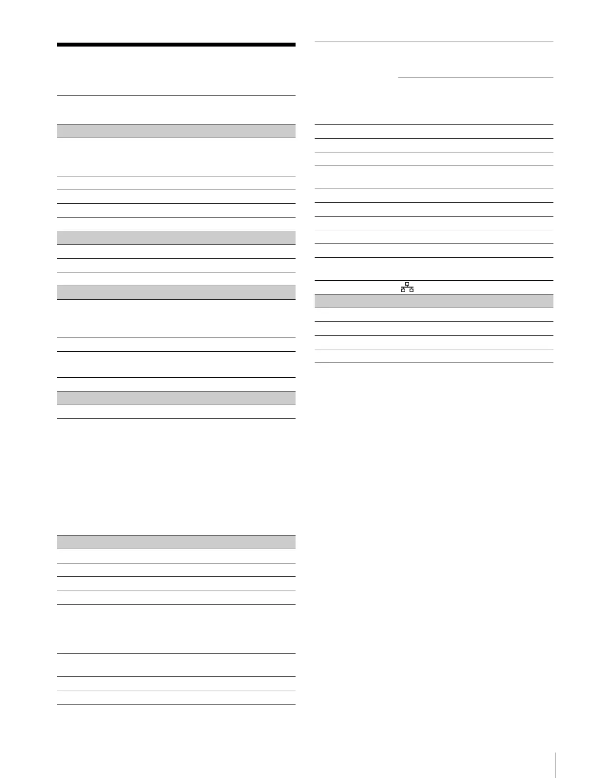
HDC2500
For the customers in the U.S.A., Canada, Europe,
Australia, and New Zealand
Connectors for optical/electric composite cables:
•LEMO
® PUW.3K.93C.TLCC96 (to the “CAMERA”
connector on CCU)
•LEMO
® FUW.3K.93C.TLMC96 (to the “CCU” connector on
CAMERA)
Caution on the optical/electric composite cable:
For connection between the camera control unit and a
camera, be sure to use an optical/electric signal composite
cable with the connectors specified in this manual in order to
comply with the limit for EMC regulations.
Pour les utilisateurs aux Etats-Unis, au Canada, en
Europe, à l’Australie, et à la Nouvelle-Zélande
Connecteurs pour les câbles optiques/électriques composites:
•LEMO
® PUW.3K.93C.TLCC96 (au connecteur
«CAMERA» de l’unité de commande de caméra)
•LEMO
® FUW.3K.93C.TLMC96 (au connecteur
«CCU» de la caméra)
Attention concernant le câble optique/électrique
composite:
Pour la connexion entre l’unité de commande de caméra et
une caméra, utilisez un câble optique/électrique composite
avec connecteurs spécifiés dans ce manuel pour assurer la
conformité avec la réglementation EMC.
General
Power requirements AC 240 V, 1.4 A (max.)
DC 180 V, 1.0 A (max.)
DC 12 V, 7 A (max.)
Operating temperature –20°C to +45°C (–4°F to 113°F)
Storage temperature –20°C to +60°C (–4°F to 140°F)
Mass Approx. 4.5 kg (9 lb 15 oz) (Unit only)
Dimensions See page 67.
Imager
Imager 2/3-type Progressive Scan CCD
Method 3-CCD, RGB
Effective resolution 1920 (horizontal) × 1080 (vertical)
Electrical characteristics
Sensitivity F10.0 with 1080/59.94i
F11.0 with 1080/50i
(at 2000 lx with 89.9% reflectivity)
Image S/N Typical –60 dB/–64 dB (NS MAX)
Horizontal resolution 1000 TV lines (at center of screen)
5% or higher modulation
Geometric distortion Negligible (not including lens distortion)
Optical system specifications
Spectral system F1.4 prism
Built-in filters Color temperature conversion filters
A: cross filter
B: 3200K(clear)
C: 4300K
D: 6300K
E: 8000K
ND filters
1: clear
2: 1/4ND
3: 1/8ND
4: 1/16ND
5: 1/64ND
Input/output connectors
CCU Optical/electrical multi-connector (1)
LENS 12-pin (1)
VF 20-pin (1)
MIC 1 IN XLR 3-pin, female (1)
AUDIO IN CH1, CH2 XLR 3-pin, female (1 each)
AUDIO switch for MIC: –60 dBu (can be
selected up to –20 dBu by menu or
HDCU2000/2500 operations), balanced
AUDIO switch for LINE: 0 dBu, balanced
INTERCOM 1,
INTERCOM 2
XLR 5-pin, female (1 each)
EARPHONE Stereo minijack (1)
DC IN XLR 4-pin (1), DC 10.5 to 17 V
DC OUT 4-pin (1), DC 10.5 to 17 V, max. 0.5 A
(This may be limited by the imposed load or
inputs.)
2-pin (1), DC 10.5 to 17 V
Max. 2.5 A
(This may be limited by the imposed load or
inputs.)
SDI 1, SDI 2 BNC-type (1-each)
SDI-MONI BNC-type (1)
TEST OUT BNC-type (1)
PROMPTER/
GENLOCK
BNC-type (1), 1 Vp-p, 75 ohms
PROMPTER2 BNC-type (1), 1 Vp-p, 75 ohms
RET CTRL 6-pin (1)
REMOTE 8-pin (1)
TRACKER 10-pin (1)
CRANE 12-pin (1)
USB USB 2.0 Type A 4-pin (1) (for connecting
USB drive)
NETWORK TRUNK RJ-45 type 8-pin (1)
Supplied accessories
Operation manual (1)
Cable clamp belt (1 set)
Camera number label (1)
Screws (+B3×8) (2)