42
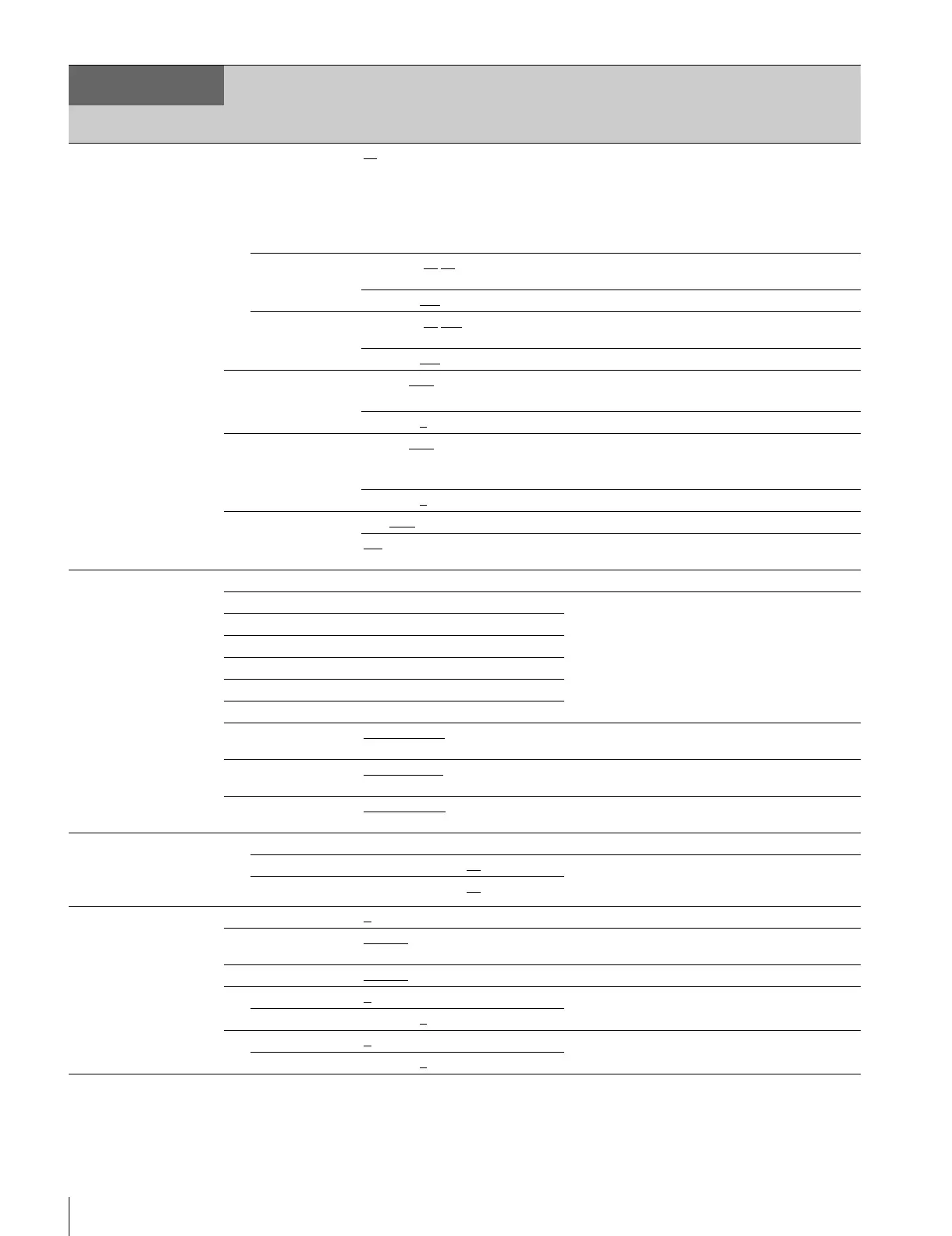
Setup Menu
<MONITOR 2>
C04
LEVEL GATE ---, 1&2, 1, 2, OFF 1&2: Displays level gate 1 & 2.
1: Displays level gate 1.
2: Displays level gate 2.
---: Displayed when camera not connected, video
output not set to CAMERA, or video output is set to
CAMERA and GATE MARKER is ON. (Display only)
Y-LEVEL1 0 to 108% 49
61 Sets the level gate 1 minimum and maximum
detection level.
–99 to 99 –25
Sets the level gate 1 zebra range.
Y-LEVEL2 0 to 108% 74
108 Sets the level gate 2 minimum and maximum
detection level.
–99 to 99 –25
Sets the level gate 2 zebra range.
GATE-MARKER ---, ON, OFF
Sets the gate signal display to ON/OFF.
---: Displayed when a camera is not connected.
–99 to 99 0
Sets the gate signal level.
MODULATION ---, ON, OFF
Sets the 4:3 aspect ratio mask function to ON/OFF
when EDGE CROP is set to ON.
---: Displayed when a camera is not connected.
–99 to 99 0
Sets the mask video level.
MARKER ON, OFF
Sets the marker signal to ON/OFF.
4:3
, 13:9, 14:9, EU VISTA, VISTA,
CINEMA, FOLLOW DC
Selects a superimposed marker signal.
<I/F SETUP>
C05
BOARD FRONT, REAR Display only
SLOT1 BOARD NAME DISPLAY Detects and displays the boards installed to the
front/rear of the CCU. (Display only)
SLOT2 BOARD NAME DISPLAY
SLOT3 BOARD NAME DISPLAY
SLOT4 BOARD NAME DISPLAY
SLOT5 BOARD NAME DISPLAY
SLOT6 BOARD NAME DISPLAY
DSUB-15 MIC-REMOTE
, WF-REMOTE Sets the output for the MIC REMOTE connector.
(HDCU2500 only)
CHARA/SYNC CHARACTER
, SYNC Sets the output for the CHARACTER/SYNC
connector. (HDCU2500 only)
REAR PREVIEW MOMENTARY
, TOGGLE Selects the REAR PREVIEW output operating
mode.
<MIC GAIN>
C06
CAM MIC GAIN Sets the microphone gain.
CH1 ---, 20, 30, 40, 50, 60
dB Settings vary depending on microphones.
---: Displayed when a camera is not connected.
(Display only)
CH2 ---, 20, 30, 40, 50, 60
dB
<AUDIO OUT>
C07
DELAY 0
to 3840FS Sets the camera’s microphone output phase.
AES/EBU OUT MIC 1/2
, AES, EBU Selects the MIC OUT DIGITAL output. (HDCU2000
only)
ANALOG OUT MIC 1/2
, AES, EBU Selects the MIC OUT ANALOG output.
CH1 LEVEL 0
, +4, –20 Sets the AUDIO CH1 output level.
ADJUST –99 to 99 0
CH2 LEVEL 0, +4, –20 Sets the AUDIO CH2 output level.
ADJUST –99 to 99 0
CCU
CONFIGURATION
Page name
Page No.
Item Settings Description

 Loading...


