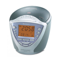
ICF-CDK70
15
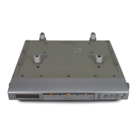
CD SECTION
RF SIGNAL CHECK
Procedure:
1. Connect the oscilloscope to TP (RF) and TP (VC) on the CD
board.
2. Insert the disc (PATD-012) (Part No. : 4-225-203-01).
3. Press the [
u
] button.
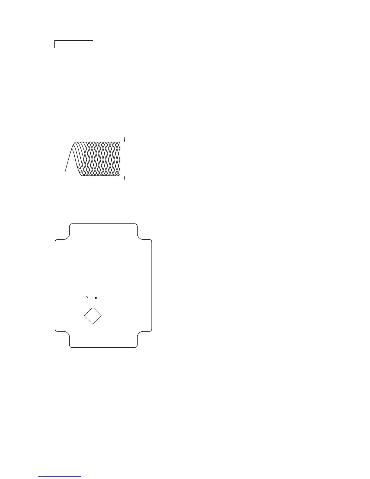
4. Confi rm that the oscilloscope waveform is as shown in the fi g-
ure below. (eye pattern)
A good eye pattern means that the diamond shape (◊) in the
center of the waveform can be clearly distinguished.
• RF signal reference waveform (eye pattern)
VOLT/DIV: 0.2 V (with the 10: 1 probe in use.)
TIME/DIV: 200 ns
0.7 to 1.7 Vp-p
When observing the eye pattern, set the oscilloscope
for AC range and raise vertical sensitivity.
Connecting Location:
IC701
TP (VC)
TP (RF)
– CD Board (Conductor Side) –
 Loading...