35
ICF-CDK70
SECTION 7
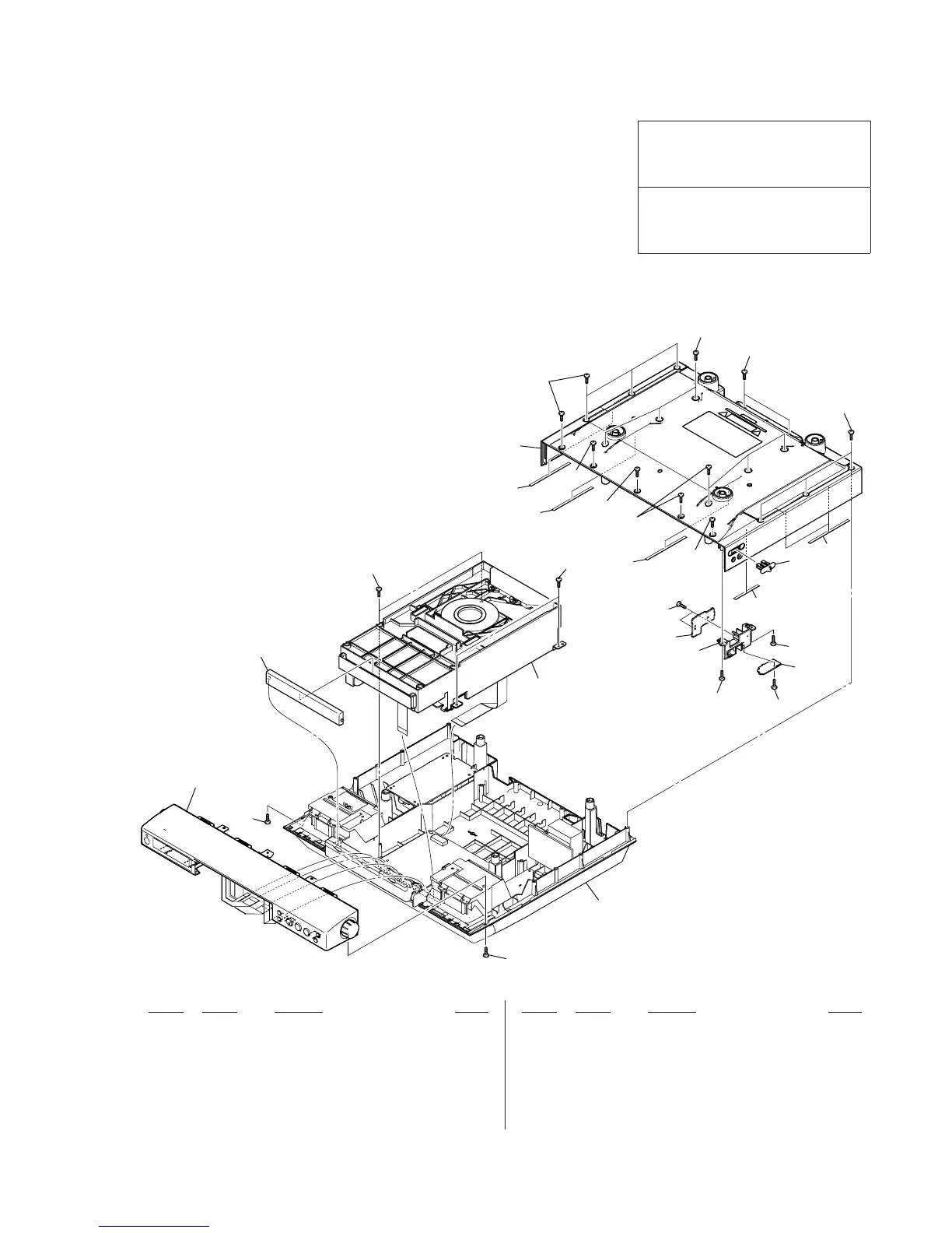
EXPLODED VIEWS
Ref. No. Part No. Description Remark Ref. No. Part No. Description Remark
Note:
• -XX and -X mean standardized parts, so
they may have some difference from the
original one.
• Items marked “*” are not stocked since
they are seldom required for routine ser-
vice.
Some delay should be anticipated when
ordering these items.
• Accessories are given in the last of the
electircal parts list.
• The mechanical parts with no reference
number in the exploded views are not sup-
plied.
• Color Indication of Appearance Parts Ex-
ample:
KNOB, BALANCE (WHITE) . . . (RED)
R R
Parts of Color Cabinet’s Color
• Abbreviation
CND: Canadian model
7-1. CABINET (UPPER) SECTION
1 2-893-517-01 COVER (TRAY)
2 3-254-151-01 SCREW (B2.6), (+) P TAPPING
3 3-254-140-01 SCREW (B2.6), (+) BV TAPPING
4 3-252-831-01 SCREW (M2.6), (+) P
5 2-893-513-01 CABINET (UPPER) (US)
5 2-893-513-11 CABINET (UPPER) (CND)
6 2-893-490-01 KNOB (MEGA BASS)
7 A-1224-512-A JACK BOARD, COMPLETE
8 3-254-081-01 SCREW
9 2-893-521-01 HOLDER (AUDIO IN)
10 A-1224-514-A MEGA BASS BOARD, COMPLETE
11 3-254-070-01 SCREW
12 3-208-071-01 CUSHION (SP BOX)
13 3-208-071-11 CUSHION (SP BOX)
The components identifi ed by mark 0
or dotted line with mark 0 are critical for
safety.
Replace only with part number specifi ed.
Les composants identifi és par une marque
0 sont critiques pour la sécurité.
Ne les remplacer que par une pièce portant
le numéro spécifi é.
1
cabinet (front) section
cabinet (lower) section
CD mechanism deck section
(DLM3A23-11)
2
2
2
2
3
3
3
3
3
3
3
4
13
5
6
7
8
8
9
10
11
11
13
13
13
12