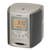
ICF-CDK70
5
SECTION 3
DISASSEMBLY
• This set can be disassembled in the order shown below.
3-1. DISASSEMBLY FLOW
Note: Follow the disassembly procedure in the numerical order shown below.
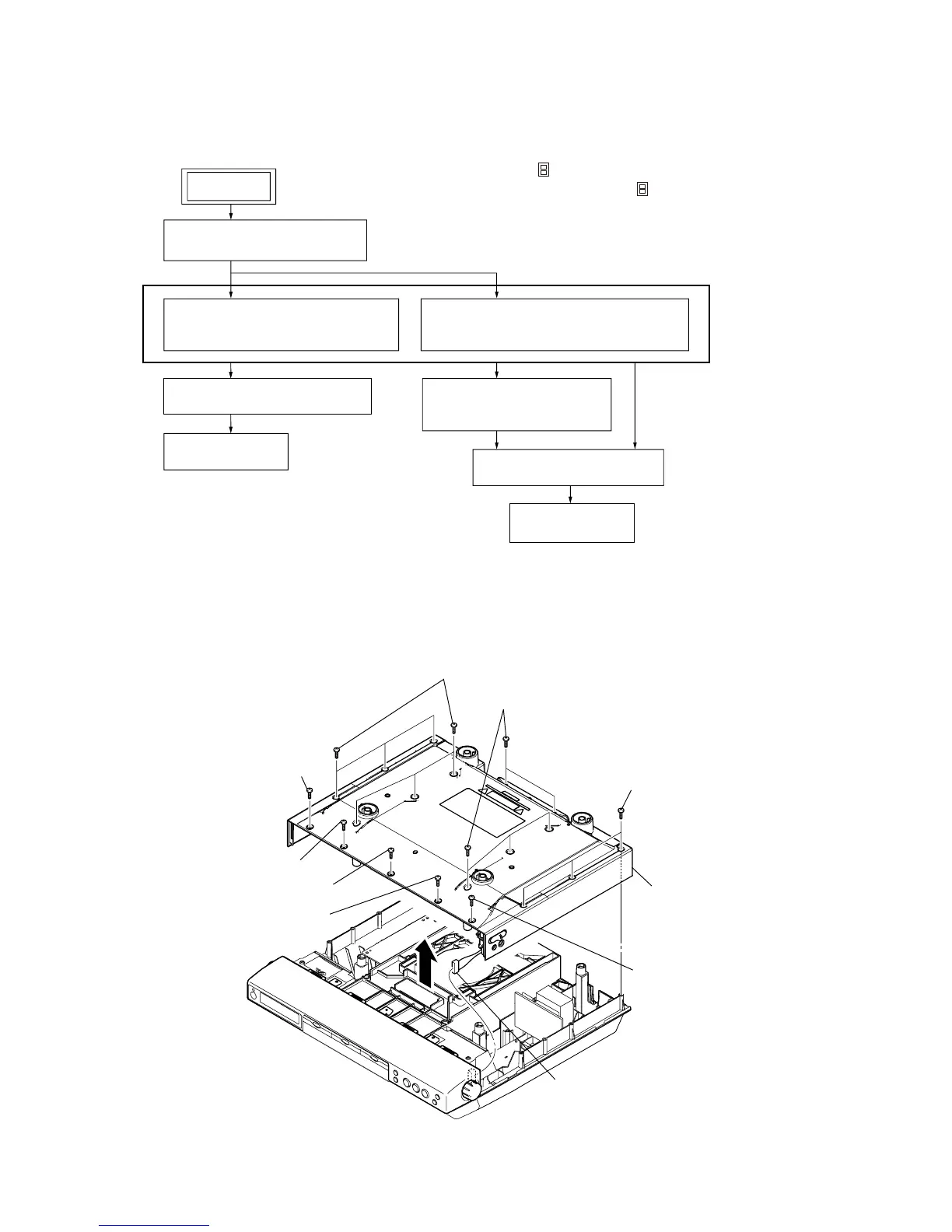
3-2. CABINET (UPPER) SECTION
3-6. CD LID ASSY
(Page 9)
SET
3-2. CABINET (UPPER) SECTION
(Page 5)
3-3. MECHANISM DECK (DLM3A23-11)
(When TRAY carries out movable.)
(Page 6)
3-4. MECHANISM DECK (DLM3A23-11)
(When TRAY does not carry out movable.)
(Page 7)
3-7. OPTICAL PICK-UP BLOCK
(KSM-213CCP)
(Page 9)
3-8. HOW TO PULL OUT TRAY
(Page 10)
3-9. BELT (DLM3A)
(Page 10)
3-5. CABINET (FRONT) SECTION
(Page 8)
Note 1: The process described in can be performed in any order.
Note 2: Without completing the process described in , the next process can not be performed.
six screws (B2.6)
screw (B2.6)
screw (B2.6)
screw (M2.6)
screw (B2.6)
connector (CN417)
screw (B2.6)
cabinet (upper) section
three screws (B2.6)
five screws (B2.6)