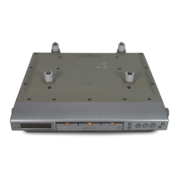
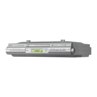
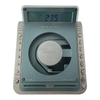
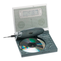
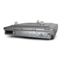
ICF-CDK70
33
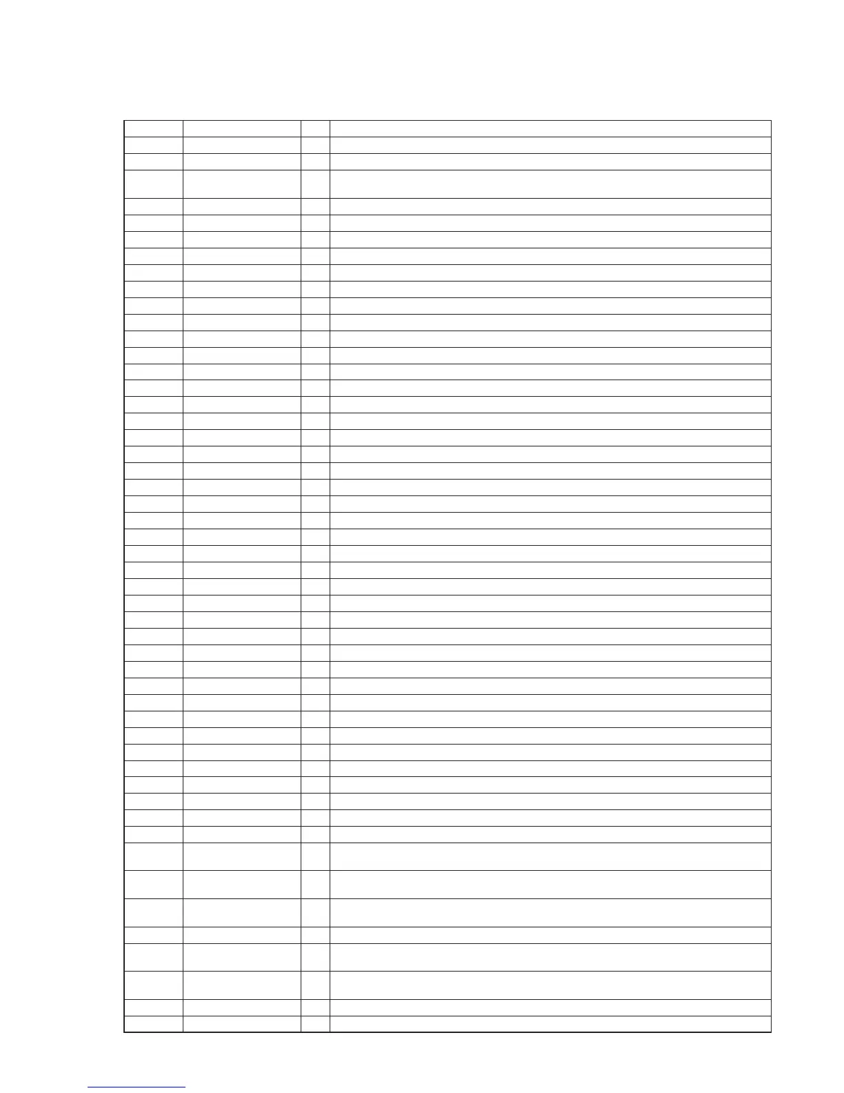
• IC Pin Function Description
MAIN BOARD IC801 MB90802PF-G-124E1 (SYSTEM CONTROLLER)
Pin No. Pin Name I/O Description
1 O-TU-DO O Serial data output to the FM/AM PLL
2 O-TU-CE O Chip enable signal output to the FM/AM PLL "L": active
3 I-CD-LIMSW I
Detection input from the sled limit-in detect switch
The optical pick-up is inner position when "L"
4 I-CD-BUSY I Busy signal input from the CD DSP
5 O-CD-DIN O Serial data output to the CD DSP
6 O-CD-MCK O Serial data transfer clock signal output to the CD DSP
7 I-CD-DOUT I Serial data input terminal
8 O-CD-RW O Data read/write selection signal output to the CD DSP
9 I-RMC I Remote control signal input from the remote control receiver
10 O-POWER CD O CD power on/off control signal output terminal "H": CD power on
11 O-AMP STANDBY O Output control signal output to the power amplifi er
12 O-4.5V CE O Not used
13 X0A I Sub system clock input terminal (32.768 kHz)
14 X1A O Sub system clock output terminal (32.768 kHz)
15 VCC - Power supply terminal (+3.3V)
16 VSS - Ground terminal
17 O-CD-XRST O System reset signal output to the CD DSP "L": reset
18 O-MO2- O Motor drive signal (-) output terminal for CAM rotation
19 O-MO2+ O Motor drive signal (+) output terminal for CAM rotation
20 O-MO1- O Motor drive signal (-) output terminal for drawer movable
21 O-MO1+ O Motor drive signal (+) output terminal for drawer movable
22 O-A MUTE O Audio muting on/off control signal output terminal "H": muting on
23 O-BUZZER O Buzzer drive signal output terminal
24 O-BASS BOOST OFF O Not used
25 I-TRSW3 I CD switch (SW3) input terminal
26 I-TRSW1 I CD switch (SW1) input terminal
27 I-TRSW7 I CD chuck switch (SW7) input terminal
28 I-TRSW2 I CD switch (SW2) input terminal
29 I-TRSW6 I CD close switch (SW6) input terminal
30 I-TRSW5 I CD stock switch (SW5) input terminal
31 I-TRSW8 I CD open switch (SW8) input terminal
32 AVCC - Power supply terminal (+3.3V) (for A/D converter)
33 O-VOL-DATA O Serial data output to the electrical volume
34 O-VOL-CLK O Serial data transfer clock signal output to the electrical volume
35 AVSS - Ground terminal (for A/D converter)
36 I-REG6.0V-CHK I Input terminal for +6V power supply voltage detection
37 I-REG4.5V-CHK I Input terminal for +4.5V power supply voltage detection
38 to 40 I-KEY0 to I-KEY2 I Front panel key input terminal (A/D input)
41 I-REG3.3V-CHK I Input terminal for CD +3.3V power supply voltage detection
42 I-AC IN I Not used
43 I-CD-SUBSYQ I Subcode Q data (80 bit serial) input from the CD DSP
44 VSS - Ground terminal
45 to 47
I-SUFFIX 0 to
I-SUFFIX 2
I Input terminal for destination discrimination
48
I-BASS BOOST ON/
OFF
I MEGA BASS switch input terminal "L": MEGA BASS on, "H": MEGA BASS off
49, 50
I-ENCODER +,
I-ENCODER -
I Jog dial pulse input from the rotary encoder (VOLUME)
51 to 53 MD2 to MD0 I Input terminal for fl ash writing mode setting
54 I-RESET I
System reset signal input from the reset signal generator "L": reset
For several hundreds msec. after the power supply rises, "L" is input, then it changes to "H"
55 to 57
O-DISC1KEY LED to
O-DISC3KEY LED
O LED drive signal output terminal
58 VLCD I Input terminal for liquid crystal display drive voltage setting
59 to 62 COM4 to COM1 O Common drive signal output to the liquid crystal display