Home
Sony
LCD TV
KF-42E200A
Page 24
Sony KF-42E200A - Page 24
114 pages
Manual
Save Page as PDF
To Next Page
To Next Page
To Previous Page
To Previous Page
Loading...
KF-42E200A/42E201A/50E200A/50E201A
KF-42E200A/42E201A/50E200A/50E201A
24
1-
910-02
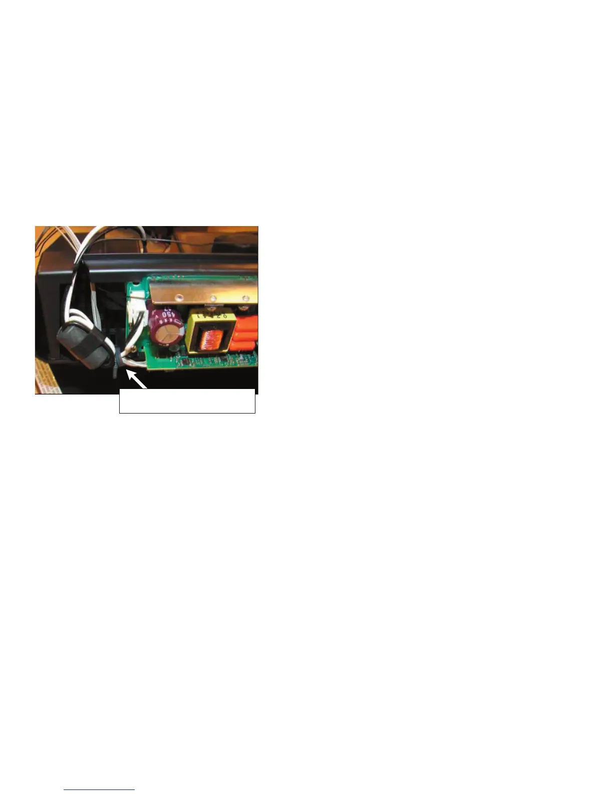
4-31 Co
nnect
or Assy sho
uld
be
dres
sed arou
nd Heat Sin
k and a
round Du
ct
Block
Cover
a
s s
hown abov
e.
BALLAST WIRE DRESSING (CONTINUED)
23
25
Table of Contents
Main Page
Service Manual
1
Table of Contents
3
Section Title
3
Specifi Cations
4
Warnings and Cautions
6
Safety Check-Out
7
Self-Diagnostic Function
8
Exiting Service Mode
12
Section 1: Disassembly
13
Overview
13
Rear Cover Removal
14
Chassis Removal and Service Position
15
G Board Removal
15
B2 Block Assembly, a Block Assembly, Antenna, U Board and K Board Removal
16
Lamp Block Assembly and Optical Block Removal
17
Lamp Connector and T2 Board Removal
18
Lamp Driver Fan Removal
19
HC Board Removal
20
HA Board and HB Board Removal
20
Screen Frame Assebmly and Speaker Removal
21
Mirror Assembly and Mirror Cover Assembly Removal
22
Wire Dressing
23
Section 2: Circuit Adjustments
36
Using the Remote Commander for Electrical Adjustments
36
Accessing Service Adjustment Mode
36
Using the Remote Commander to Change Service Data
36
Exiting Service Mode
37
Verifying Service Data Changes
37
H/V Center Confi Rmation and Adjustments
37
IRIS Adjustments
38
Section 3: Diagrams
39
Circuit Boards Location
39
Printed Wiring Boards and Schematic Diagrams Information
39
Signal Flow Block Diagram
41
Schematics and Supporting Information
42
A Board Schematic Diagram
42
B2 Board Schematic Diagram (1 of 7)
44
B2 Board Schematic Diagram (2 of 7)
45
B2 Board Schematic Diagram (3 of 7)
46
B2 Board Schematic Diagram (4 of 7)
47
B2 Board Schematic Diagram (5 of 7)
48
B2 Board Schematic Diagram (6 of 7)
49
B2 Board Schematic Diagram (7 of 7)
50
G Board Schematic Diagram (1 of 2)
52
G Board Schematic Diagram (2 of 2)
53
HA Board Schematic Diagram
56
HB Board Schematic Diagram
58
HC Board Schematic Diagram
60
K Board Schematic Diagram
62
S2 Board Schematic Diagram
65
T1 Board Schematic Diagram
68
T2 Board Schematic Diagram
68
U Board Schematic Diagram
73
Semiconductors
75
Section 4: Exploded Views
76
Covers
76
Chassis
77
Optics Unit Block Assembly and Lamp Assembly
78
Section 5: Electrical Parts List
79
Appendix A: Replacing the Lamp
111
Related product manuals
Sony KD-43X85K
120 pages
Sony KD-85X80L
61 pages
Sony KLV-23HR3
2 pages
Sony KD-43X80L
61 pages
Sony KD-43X80K
95 pages
Sony KLV-27HR3
56 pages
Sony KD-60X690E
71 pages
Sony KD-70X690E
71 pages
Sony KDL-40XBR5
2 pages
Sony KD-60X695E
71 pages
Sony KDL-40XBR6
107 pages
Sony KLV-S40A10
68 pages