- 19 -
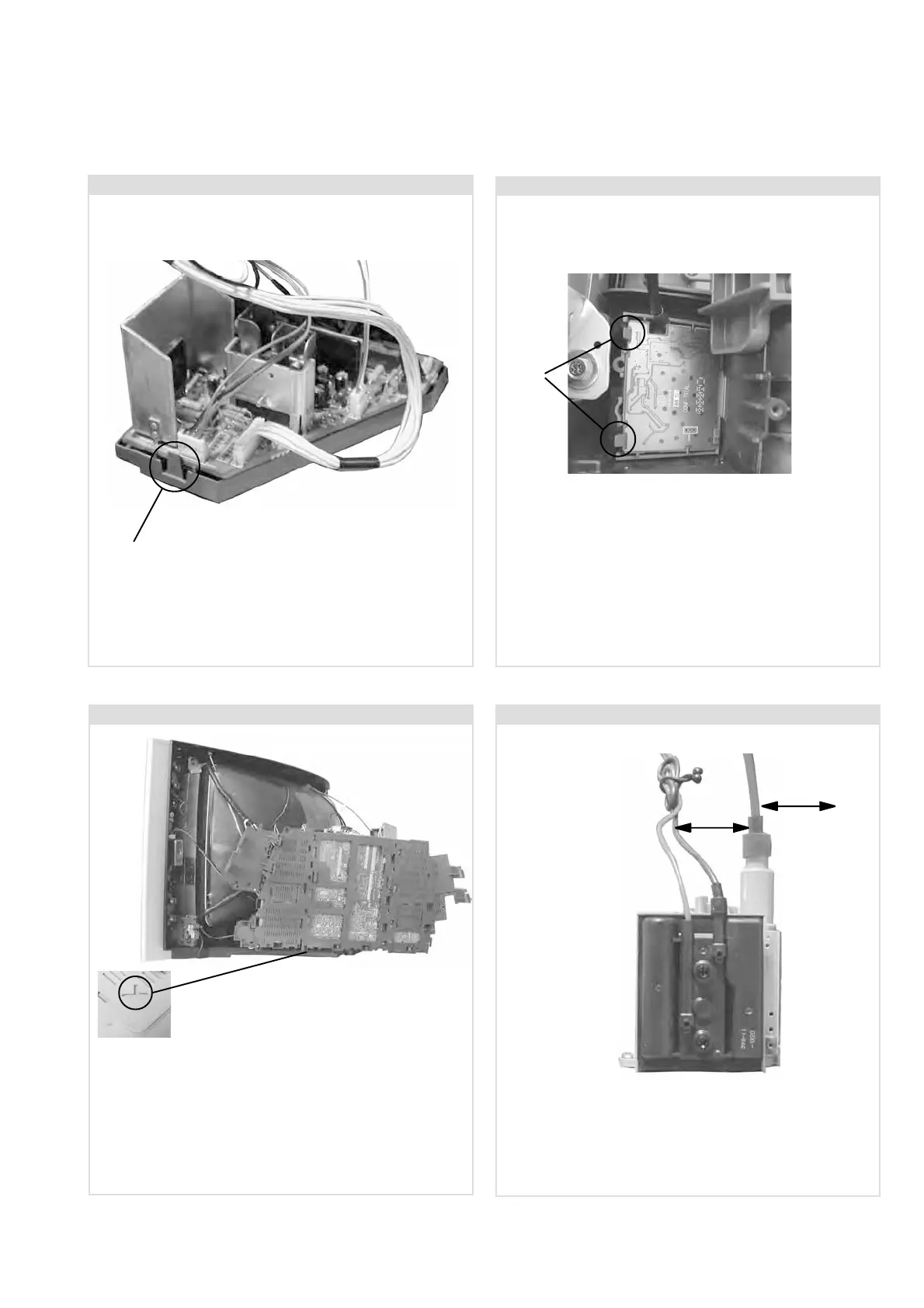
2-10. Service Position
To place the chassis in the service position, remove the
SF and MS3 boards from their brackets (see 2-8 and 2-9.),
remove the G1 and D2 brackets and position on the side of
the main bracket as shown above. Insert the main bracket
firmly into the T-slot located on the left corner of the beznet as
indicated (see inset). To gain access to the underside of the
boards follow the instructions on page 21. [Removal and
Replacement of the main bracket bottom plates].
2-9. MS3 Board Removal
To remove the MS3 board release the two clips circled and
ease the board gently away from the support bracket.
2-8. SF Board Removal
To remove the SF board release the clip circled and
ease the board gently away from the support bracket.
2-11. Wire Dressing
Ensure that wires do not touch heatsinks and high temperature
hotspots. All wires must be kept at a minimum distance of
20mm away from the EHT lead
20mm
20mm
Clips
Clip
 Loading...