25
MC-S50
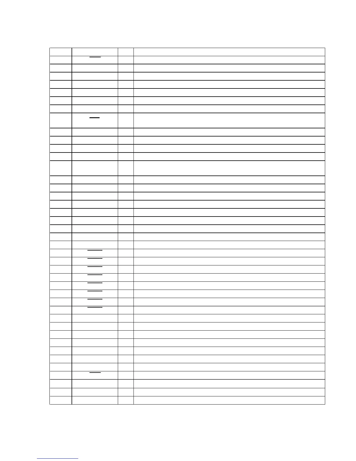
• LOGIC BOARD IC801 HD6433800A02FP (CPU)
Pin No. Pin Name I/O
Description
1 IRQ1 I
Voltage detect input terminal
2X1I
Sub system clock input terminal (32.768kHz)
3X2O
Sub system clock output terminal (32.768kHz)
4 VSS
— Ground terminal
5 OSC1
O Main system clock output terminal (8MHz)
6 OSC2
I Main system clock input terminal (8MHz)
7 TEST
I Test mode signal input terminal Not used (fixed at “L” )
8 RES I
System reset signal input from the reset signal generator (IC802) “L”: reset
For several hundreds msec. after the power supply rises, “L” is input, then it changes to “H”
9 P31 —
Not used (open)
10 P32 O
Power supply (V2) ON/OFF control signal output terminal “L”: ON
11 P33
O Interrupt request signal output to the digital signal processor (IC601)
12, 13 P34, P35 —
Not used (fixed at “L” )
14 P36
O
Reset signal output to the digital signal processor (IC601) and EEPROM (IC603)
“L”: reset
15 P37
O Power supply (VCORE) ON/OFF control signal output terminal “L”: ON
16 VCC
— Power supply terminal (+3.2V)
17 V1
— Power supply terminal for the liquid crystal display (open in this set)
18 V2
— Power supply terminal for the liquid crystal display (connected to pin ql (V3))
19 V3
— Power supply terminal for the liquid crystal display (connected to pin qk (V2))
20, 21 COM4, COM3
O Common signal output to the liquid crystal display Not used (open)
22, 23 COM2, COM1
O Common signal output to the liquid crystal display (LCD901)
24, 25 SEG25, SEG24
O Segment signal output to the liquid crystal display Not used (open)
26 to 40 SEG23 to SEG9 O
Segment signal output to the liquid crystal display (LCD901)
41 WKP7
I USB connection detect signal input terminal
42 WKP6
I MEGA BASS/AVLS switch (S807) input terminal “L”: NORM
43 WKP5
I . key (S806) input terminal
44 WKP4
I > key (S805) input terminal
45 WKP3
I Nx key (S804) input terminal
46 WKP2
I MODE key (S803) input terminal
47 WKP1
I VOL - key (S802) input terminal
48 WKP0
I VOL + key (S801) input terminal
49 P90
O LCD back light (D801) ON/OFF control signal output terminal “H”: LED ON
50 to 54 P91 to P95 —
Not used (open)
55 VSS
— Ground terminal
56 IRQACE
I Interrupt request signal input terminal Not used (fixed at “L” )
57 SCK
I Serial clock signal input from the digital signal processor (IC601)
58 RXD
I Serial data receive signal input from the digital signal processor (IC601)
59 TXD
O Serial data transmit signal output to the digital signal processor (IC601)
60 IRQ0
I Serial clock signal input from the digital signal processor (IC601)
61 AVCC
— Power supply terminal (+3.2V) (for the analog)
62 AN0
I Battery voltage detect input terminal
63, 64 PB1, PB2
I Not used (fixed at “L” )
 Loading...