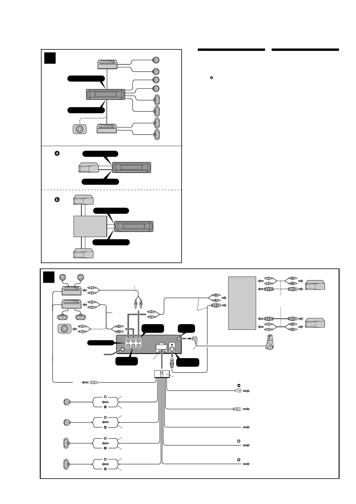
Connection example (2)
Notes (2-A)
• Be sure to connect the ground lead before connecting
the amplifier.
• If you connect an optional power amplifier and do not
use the built-in amplifier, the beep sound will be
deactivated.
Tip (2-B-
)
For connecting two or more MD/CD changers, the source
selector XA-C30 (optional) is necessary.
Connection diagram (3)
1
To a metal surface of the car
First connect the black ground lead, then connect
the yellow and red power input leads.
2 To the power antenna control lead or power
supply lead of antenna booster amplifier
Notes
• It is not necessary to connect this lead if there is no
power antenna or antenna booster, or with a
manually-operated telescopic antenna.
•When your car has a built-in FM/AM antenna in
the rear/side glass, see “Notes on the control and
power supply leads.”
3
To AMP REMOTE IN of an optional power
amplifier
This connection is only for amplifiers. Connecting
any other system may damage the unit.
4
To the interface cable of a car telephone
5
To the +12 V power terminal which is energized
in the accessory position of the ignition key
switch
Notes
• If there is no accessory position, connect to the +12
V power (battery) terminal which is energized at
all times.
Be sure to connect the black ground lead to a
metal surface of the car first.
•When your car has a built-in FM/AM antenna in
the rear/side glass, see “Notes on the control and
power supply leads.”
6
To the +12 V power terminal which is energized
at all times
Be sure to connect the black ground lead to a metal
surface of the car first.
Notes on the control and power supply leads
• The power antenna control lead (blue) supplies +12 V
DC when you turn on the tuner.
•When your car has built-in FM/AM antenna in the rear/
side glass, connect the power antenna control lead
(blue) or the accessory power input lead (red) to the
power terminal of the existing antenna booster. For
details, consult your dealer.
•A power antenna without a relay box cannot be used
with this unit.
Memory hold connection
When the yellow power input lead is connected, power
will always be supplied to the memory circuit even when
the ignition switch is turned off.
Notes on speaker connection
• Before connecting the speakers, turn the unit off.
• Use speakers with an impedance of 4 to 8 ohms, and
with adequate power handling capacities to avoid its
damage.
• Do not connect the speaker terminals to the car
chassis, or connect the terminals of the right speakers
with those of the left speaker.
• Do not connect the ground lead of this unit to the
negative (–) terminal of the speaker.
• Do not attempt to connect the speakers in parallel.
• Connect only passive speakers. Connecting active
speakers (with built-in amplifiers) to the speaker
terminals may damage the unit.
•To avoid a malfunction, do not use the built-in speaker
leads installed in your car if the unit shares a common
negative (–) lead for the right and left speakers.
• Do not connect the unit’s speaker leads to each other.
Note on connection
If speaker and amplifier are not connected correctly,
“FAILURE” appears in the display. In this case, make sure
the speaker and amplifier are connected correctly.
Max. supply current 0.3 A
Max. supply current 0.1 A
or SUB.
instructions.
Insert with the cord downwards.
 Loading...