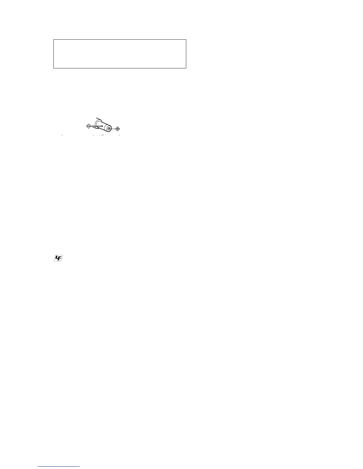
Polarity of the
plug
TABLE OF CONTENTS
1. SERVICING NOTES ............................................... 4
2. GENERAL ................................................................... 5
3. DISASSEMBLY
3-1. Disassembly Flow ........................................................... 6
3-2. Case (Lower) ................................................................... 7
3-3. Upper Panel Section........................................................ 7
3-4. LCD Module, Upper Panel Sub Assy ............................. 8
3-5. Mechanism Deck (MT-MZN707-177) ........................... 8
3-6. Set Chassis (5192) Assy.................................................. 9
3-7. MAIN Board ................................................................... 9
3-8. OP Service Assy (LCX-5R) ............................................ 10
3-9. Holder Assy ..................................................................... 11
3-10. DC Motor (Sled) (M602) ................................................ 11
3-11. DC SSM18B Motor (Spindle) (M601),
DC Motor (Over Write Head Up/Down) (M603) .......... 12
4. TEST MODE.............................................................. 13
5. ELECTRICAL ADJUSTMENTS......................... 19
6. DIAGRAMS
6-1. Block Diagram – SERVO/USB Section – ...................... 32
6-2. Block Diagram – AUDIO Section – ............................... 33
6-3. Block Diagram – DISPLAY/KEY CONTROL/
POWER SUPPLY Section – ........................................... 34
6-4. Note for Printed Wiring Board and
Schematic Diagrams ....................................................... 35
6-5. Printed Wiring Board
– MAIN Board (Component Side) – ............................. 36
6-6. Printed Wiring Board
– MAIN Board (Conductor Side) – ............................... 37
6-7. Schematic Diagram – MAIN Board (1/4) – .................. 38
6-8. Schematic Diagram – MAIN Board (2/4) – .................. 39
6-9. Schematic Diagram – MAIN Board (3/4) – .................. 40
6-10. Schematic Diagram – MAIN Board (4/4) – .................. 41
6-11. IC Pin Function Description ........................................... 48
7. EXPLODED VIEWS
7-1. Upper Panel, Case (Lower) Section ............................... 55
7-2. Chassis Section ............................................................... 56
7-3. MAIN Board Section ...................................................... 57
7-4. Mechanism Deck Section-1 (MT-MZN707-177)........... 58
7-5. Mechanism Deck Section-2 (MT-MZN707-177)........... 59
8. ELECTRICAL PARTS LIST ............................... 60
CAUTION
Use of controls or adjustments or performance of procedures
other than those specified herein may result in hazardous ra-
diation exposure.
Notes on chip component replacement
• Never reuse a disconnected chip component.
• Notice that the minus side of a tantalum capacitor may be dam-
aged by heat.
Flexible Circuit Board Repairing
• Keep the temperature of the soldering iron around 270 ˚C dur-
ing repairing.
• Do not touch the soldering iron on the same conductor of the
circuit board (within 3 times).
• Be careful not to apply force on the conductor when soldering
or unsoldering.
UNLEADED SOLDER
Boards requiring use of unleaded solder are printed with the lead-
free mark (LF) indicating the solder contains no lead.
(Caution: Some printed circuit boards may not come printed with
the lead free mark due to their particular size)
: LEAD FREE MARK
Unleaded solder has the following characteristics.
• Unleaded solder melts at a temperature about 40 ˚C higher than
ordinary solder.
Ordinary soldering irons can be used but the iron tip has to be
applied to the solder joint for a slightly longer time.
Soldering irons using a temperature regulator should be set to
about 350 ˚C .
Caution: The printed pattern (copper foil) may peel away if the
heated tip is applied for too long, so be careful!
• Strong viscosity
Unleaded solder is more viscous (sticky, less prone to flow) than
ordinary solder so use caution not to let solder bridges occur
such as on IC pins, etc.
• Usable with ordinary solder
It is best to use only unleaded solder but unleaded solder may
also be added to ordinary solder.
 Loading...