PHA-1A/1AEU
20
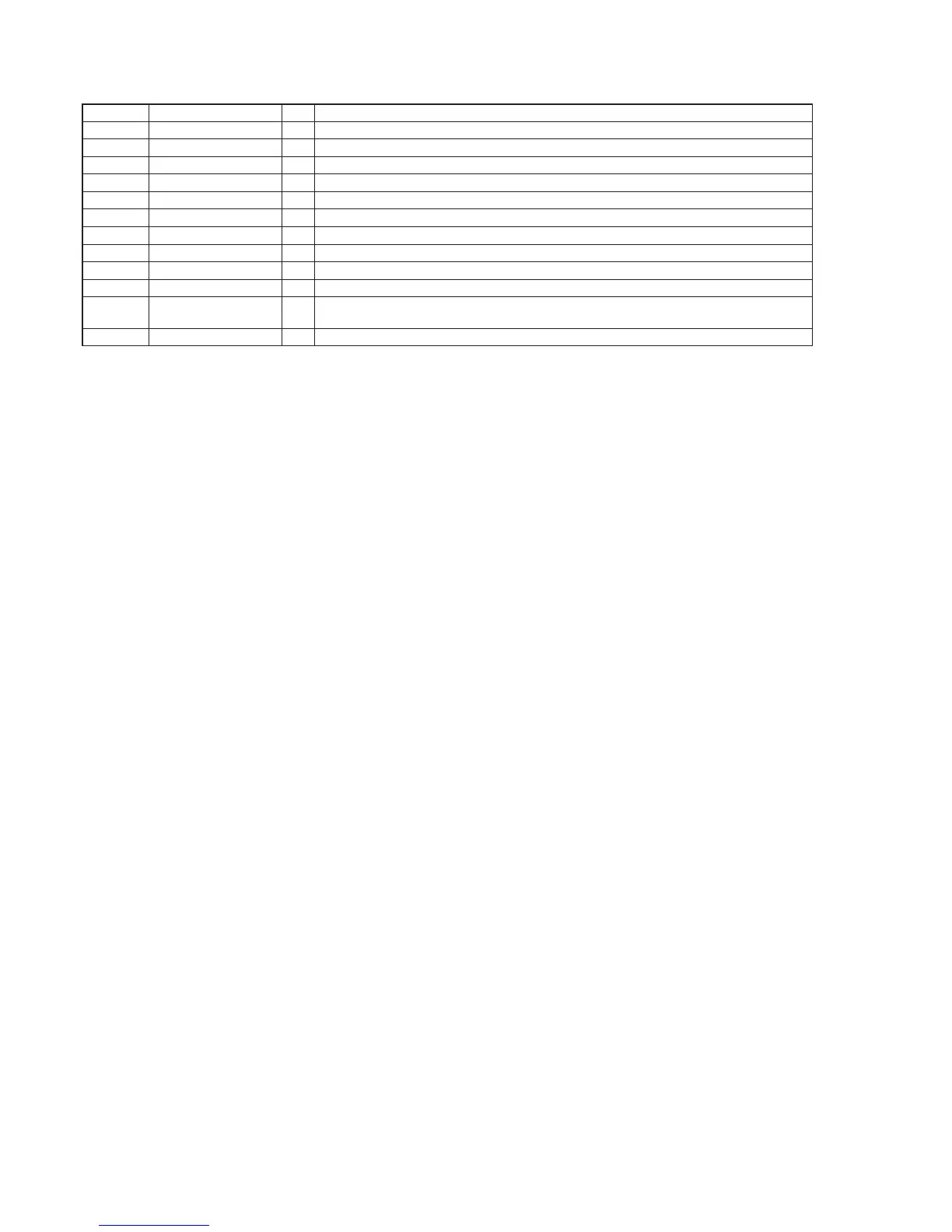
Pin No. Pin Name I/O Description
87 X2DAC_SCLK I/O I2S bit clock signal input/output terminal Not used
88 X2DAC_SDOUT O I2S serial data output terminal Not used
89 XMDAC_SDOUT0 O Digital audio data output to the USB controller
90 to 92 NC - Not used
93 XMDAC_SCLK O Digital audio bit clock signal output to the USB controller
94 XMDAC_LRCK O Digital audio L/R sampling clock signal output to the USB controller
95 XMDAC_MCLK O Digital audio master clock signal output to the USB controller
96 XSEL_PWR I Power selection signal input terminal “L”: bus power, “H”: self power Fixed at “H” in this unit
97 VCC3V - Power supply terminal (+3.3V) (digital system)
98 XRST I Reset signal input terminal Not used
99 XTEST I
Test mode selection signal input terminal “L”: normal operation, “H”: test mode
Fixed at “L” in this unit
100 XSCI I System clock input terminal (12 MHz)