14
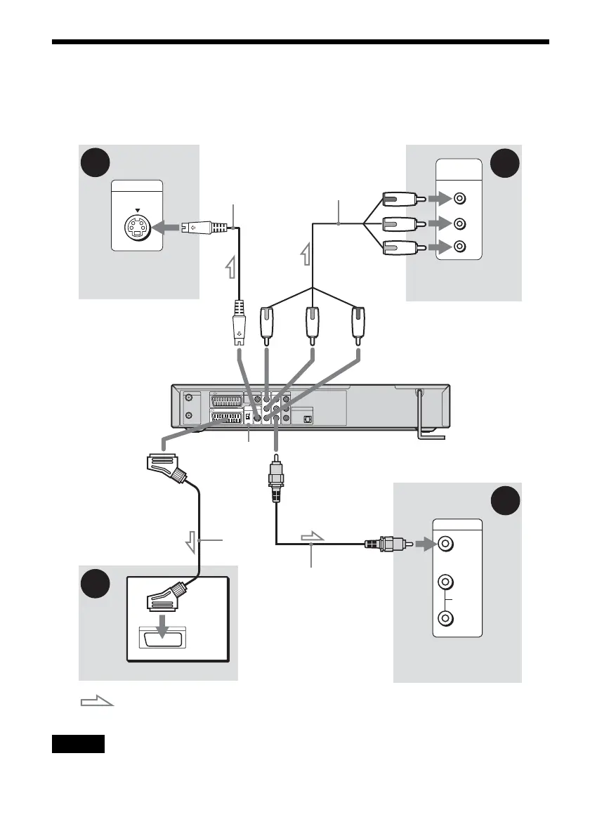
Step 3: Connecting the Video Cords
Select one of the following patterns A through D, according to the input jack on your TV monitor,
projector, or AV amplifier (receiver). This will enable you to view pictures. Audio connections are
explained in “Step 4: Connecting the Audio Cords” (page 16).
Note
Do not connect more than one type of video cord between the recorder and your TV at the same time.
INPUT
S VIDEO
P
R
P
B
Y
COMPONENT
VIDEO IN
VIDEO
AUDIO
INPUT
L
R
AERIAL
IN
OUT
LINE 3 / DECODER
DIGITAL OUT
LINE 1
-
TV
COAXIAL
PCM/DTS/
MPEG/
DOLBY DIGITAL
PCM/DTS/MPEG/
DOLBY DIGITAL
COMPONENT
VIDEO OUT
P
B
/C
B
P
R
/C
R
Y
LINE 2 OUT
L
AUDIO
VIDEO
R
LINE 4 IN
L
AUDI O
VIDEO
R
DIGITAL OUT
VIDEO OUT
SELECT
RGB
COMPO-
NENT
OPTICAL
S VIDEO
LINE 2 OUT
C
D
B
A
Video
cord (supplied)
Component video
cord (not supplied)
TV, projector, or AV
amplifier (receiver)
TV, projector, or AV
amplifier (receiver)
(green)
S-video cord
(not supplied)
TV, projector, or AV
amplifier (receiver)
(blue) (red)
(green)
(blue)
(red)
: Signal flow
to COMPONENT
VIDEO OUT
to LINE 2 OUT
(S VIDEO)
to LINE 2 OUT (VIDEO)
VIDEO OUT
SELECT switch
DVD recorder
TV
SCART
cord (not
supplied)
to i
LINE1-TV
 Loading...