6-2
2-1-5. Input/Output Levels and Impedance
Video input: LINE-1 (TV)/LINE-2 IN/LINE-3 IN
Input signal: 1 Vp-p, 75 ohms, unbalanced,
sync negative
Video output: LINE-1 (TV)
Output signal: 1 Vp-p, 75 ohms, unbalanced,
sync negative
Audio input: LINE-1 (TV)/LINE-2 IN/LINE-3 IN
Input level: –7.5 dBs
(0 dBs= 0.775 Vrms)
Input impedance: more than 47 kilohms
Audio output:LINE-1 (TV)
Standard level: –7.5 dBs at load impedance 47
kilohms
Output impedance: less than 10 kilohms
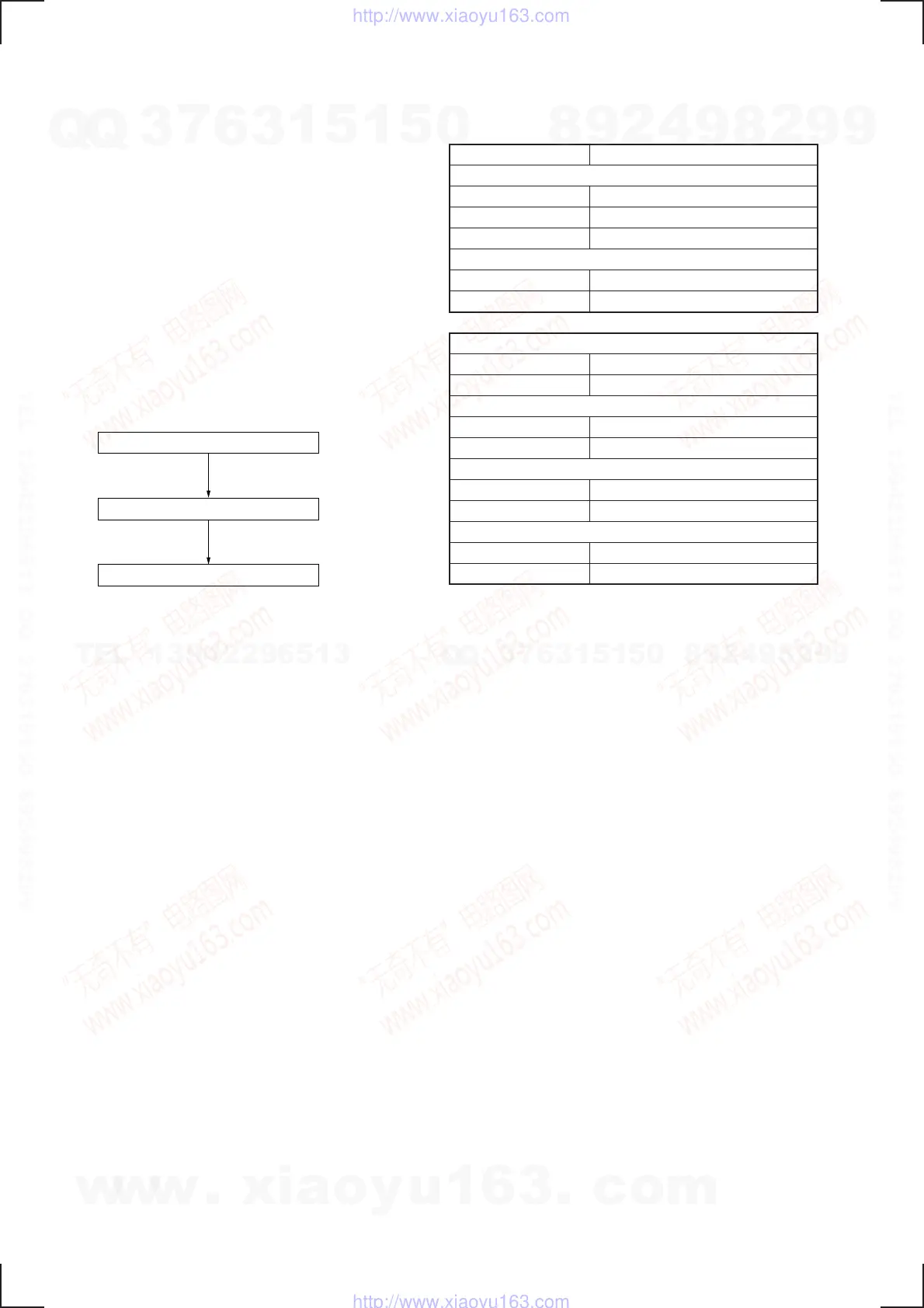
2-1-6. Adjustment Sequence
The adjustments should be performed in the following sequence.
2-2. POWER SUPPLY CHECK
2-2-1. Output Voltage Check (MA-338 Board)
Mode STANDBY
+30 V Check
Measurement point CN600 pin 1
Specified value 31.0 to 39.0 V
Mode E-E
+6 V Check
Measurement point Corrector of Q600
Specified value 5.56 to 6.25 V
–11 V Check
Measurement point Corrector of Q602
Specified value –13.5 to – 9.5 V
+12 V Check
Measurement point IC600 pin 2
Specified value 11.7 to 12.3 V
+5 V Check
Measurement point Emitter of Q600
Specified value 4.8 to 5.4 V
MTR12 V Check
Measurement point Corrector of Q601
Specified value 12.6 to 14.6 V
[Check Method]
1) Each of these supply voltages must meet its specified value.
Power Supply Check
Servo System Adjustments
Audio System Adjustments
w
w
w
.
x
i
a
o
y
u
1
6
3
.
c
o
m
Q
Q
3
7
6
3
1
5
1
5
0
9
9
2
8
9
4
2
9
8
T
E
L
1
3
9
4
2
2
9
6
5
1
3
9
9
2
8
9
4
2
9
8
0
5
1
5
1
3
6
7
3
Q
Q
TEL 13942296513 QQ 376315150 892498299
TEL 13942296513 QQ 376315150 892498299
http://www.xiaoyu163.com
http://www.xiaoyu163.com