8
SPP-A1070/A1071
4. Data Link
Data bits are encoded in manchester format for which bit “0” is
represented by 500 µs low and 500 µs high while bit “1” by 500
µs high and 500 µs low.
If data transmission is enabled, it will transmit data packet with
the following fields continuously.
(“0”=500 µs low and “1”=500 µs high)
• 8 bit preamble :0101010101010101
• 8 bit word sync :0110010010010110
• 20 bit security code :Restored from EEPROM
• 4 bit reserved data :01010101
• 8 bit command :0101010101010101
• 8 bit data :0101010101010101
If data transmission is enabled, it will toggle the [LINE] LED every
time when a data packet is received. (No security code would be
checked)
HANDSET
1. Entering the Manual Test Mode
1. Press the [PGM] key.
2. Select the “DIAL MODE” menu by pressing v or V keys.
3. Press the key sequence [SELECT], [2], [1], [0], [4].
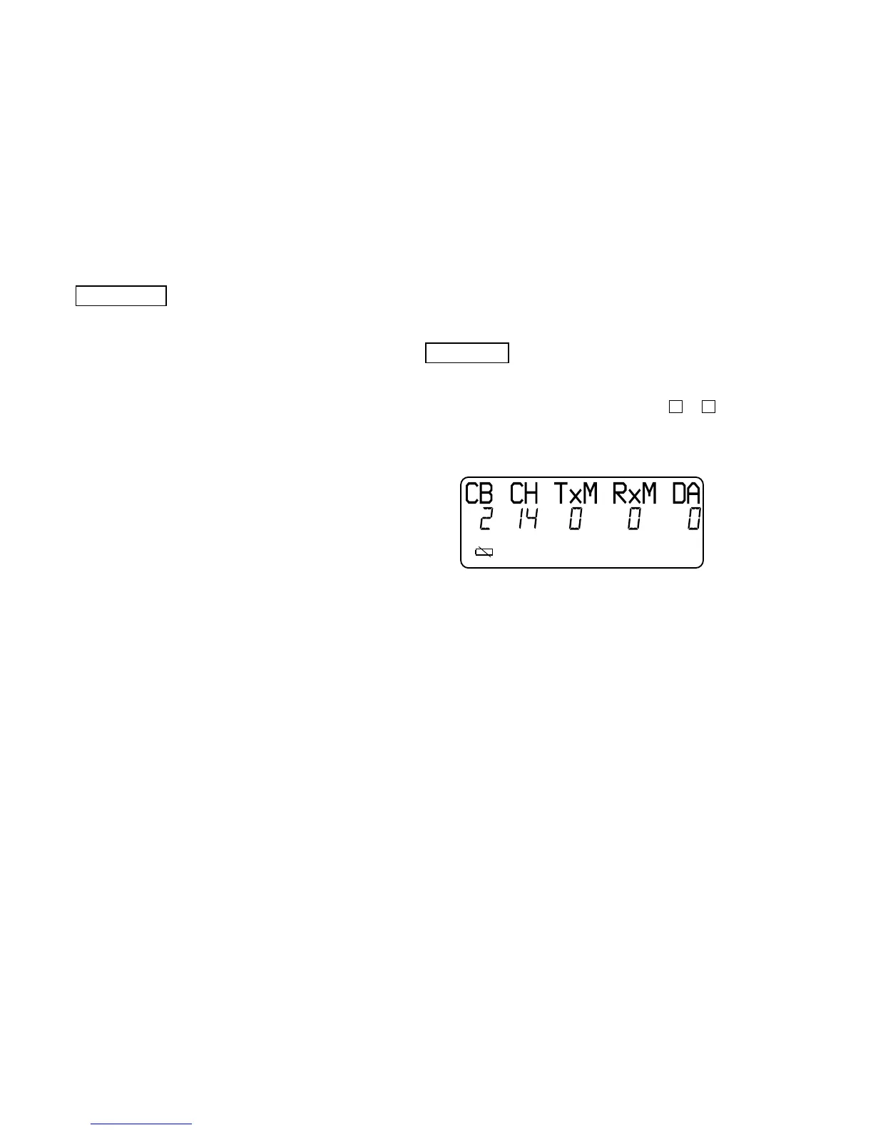
4. When enter the test mode, happy tone is emitted, and the LCD
displays as shown below.
2. Default Settings
• Channel set to 14. (out of 00 to 29)
• Combo set to active mode.
(0: inactive mode, 1: RX mode, 2: active mode)
• TX audio path unmuted. (0: unmuted, 1: muted)
• RX audio path unmuted. (0: unmuted, 1: muted)
• Date transmission disabled. (0: disabled, 1: enabled)
• Battery detection.
(“E” icon on: RSSI detection, “E” icon off: battery detection)
SECTION 4
TEST MODE
Introduction
The manual test mode can be used for testing the RF and audio
sections of the base unit and handset. The manual test mode is
also required for the FCC testing in which the phone is tested for
interference at the first, middle, and last RF channels.
The following features are provided in manual test mode.
• Able to set operating mode of the combo chip.
• Able to mute or unmute the audio path.
• Able to change the RF channel. (Both RX and TX)
• Able to transmit or receive data packet.
• Able to synchronize the security code.
BASE UNIT
1. Entering the Manual Test Mode
1. While pressing the [HANDSET LOCATOR] key, turn the
power on, then releasing and pressing it again within 2
seconds.
2. When enter the test mode, the [LINE] LED blinks slowly.
2. Default Settings
• Channel set to 14. (out of 0 to 29)
• Combo set to active mode.
• TX audio path unmuted.
• RX audio path unmuted.
• Off hooked.
• Date transmission disabled.
3. HANDSET LOCATOR Key Operation
1.
Condition: Press the [HANDSET LOCATOR] key while the [LINE]
LED lights up.
Operation: Advance channel by one, following 15, 16, 17...28, 29,
0, 1....
Indication:LED remains on for 3 seconds and then blinks again.
2.
Condition: Press the [HANDSET LOCATOR] key while the [LINE]
LED goes off.
Operation: Toggle combo between active mode and RX mode.
Indication:LED remains off for 3 seconds and then blinks again.
3.
Condition: Press the [HANDSET LOCATOR] key over 2 seconds.
Operation: Enable data transmission.
Set combo to active mode.
Indication:LED toggles once and then remains steady.
4.
Condition: Press the [HANDSET LOCATOR] key while data
transmission is enabled.
Operation: Disable data transmission.
Set combo to RX mode.
Indication:LED is on for 1 seconds and then blinks again.
5.
Condition: Power down.
Operation: Release the test mode