28
2-2 Connector Panel
Chapter 2 Locations and Functions of Parts
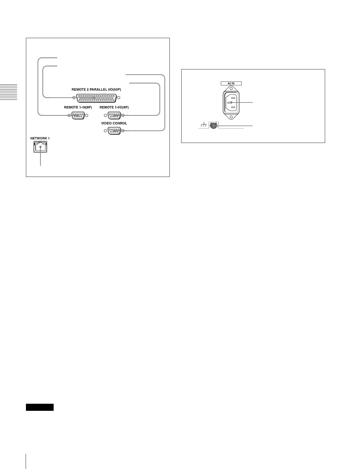
3 Remote input/output section
a REMOTE 1-IN(9P) connector (D-sub 9-pin,
female)
Use this, with the supplied 9-pin remote control cable, to
connect the unit to another SRW-5000/5500 unit or
another HD VTR unit to carry out editing with a BVE-
series editor BVE-900/910/2000/9000/9100.
b REMOTE 2 PARALLEL I/O(50P) connector (D-
sub 50-pin, female)
Inputs an external remote control signal.
For details, refer to the Maintenance Manual Volume 1.
c VIDEO CONTROL (Digital Video Processor
Control) connector (D-sub 9-pin, female)
Connects to the optional HKDV-900 HD Digital Video
Controller to enable remote control of the internal digital
video processor. Turn off the power before connecting the
remote controller.
d REMOTE 1-I/O(9P) connector (D-sub 9-pin,
female)
Use this, with the supplied 9-pin remote control cable, to
connect the unit to another SRW-5000/5500 unit or
another HD VTR unit to carry out editing with a BVE-
series editor BVE-700/2000/9000/9100.
e NETWORK 1 connector
Used for monitoring the VTR by SNMP, or for setting or
changing VTR settings by HTTP.
• For safety, do not connect the connector for peripheral
device wiring that might have excessive voltage to this
port. Follow the instructions for this port.
• When you connect the NETWORK cable of the unit to
peripheral device, use a shielded-type cable to prevent
malfunction due to radiation noise.
4 Power supply
a AC IN connector
Connects to an AC outlet using an appropriate power cord.
b U Ground terminal
CAUTION
1 REMOTE1-IN(9P) connector
2 REMOTE 2 PARALLEL I/O(50P) connector
3 VIDEO CONTROL connector
4 REMOTE1-I/O(9P) connector
5 NETWORK 1 connector
1 AC IN connector
2 U Ground terminal