STR-KM22/KM55/KM77
5
CAPACITOR ELECTRICAL DISCHARGE PROCESSING
When checking the board, the electrical discharge is necessary for
the electric shock prevention.
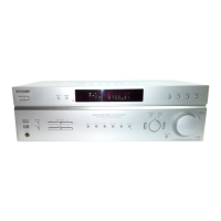
Connect the resistor to both ends of respective capacitors.
• Main Board
C930, C931
• Sub Rectifi er Board
C943, C944 (STR-KM55/KM77 only)
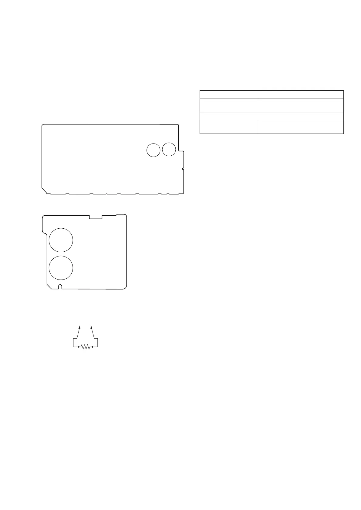
MAIN BOARD (Conductor Side) –
(To both ends of each capacitor)
800 :/2 W
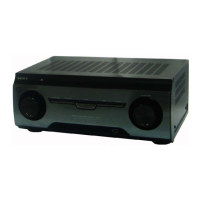
C943
C931
C930
C944
RECTIFIER BOARD (Conductor Side) –
NOTE OF REPLACING MAIN BOARD
When Main board are replaced, please perform below procedure:
1. While pressing the [SPEAKER SETTING] and [GAME] but-
tons, Press the [
?/1
] button to turn on the main power.
If the setting is not fi xed with its model or destination or both
(model+destination), the message below will appears.
Items Display
MODEL + AREA NOT
FIX
MD.D S T. U N F I X
MODEL NOT FIX
M O D E L. U N F I X
AREA/DESTINATION
NOT FIX
DEST. UNF I X
If the model and area already been fi xed, below two steps will
perform.
2. The message “MV2 **” appears. This is main microprocessor
version (KM22).
The message “MV5 **” appears. This is main microprocessor
version (KM55).
The message “MV7 **” appears. This is main microprocessor
version (KM77).
3. Each time the [DISPLAY] button is pressed, “SYS.
vx.xxx”,“MAIN vx.xx”, “VIDEO vx.xx”, “SFLASH vx.xx”,
“STUNE vx.xx”, BTM vx.xx and BTL vx.xx appear in this
order, and returns to the “MV** xxx” display.
**: destination, x.xxx: software version