screw
4. Enter the FWD mode and perform steps 1 to 3.
5. Check that the phase difference between L-CH and R-CH is in
the range of in-phase to 90°.
6. After adjustment, lock the screw with locking compound.
Adjustment Location:
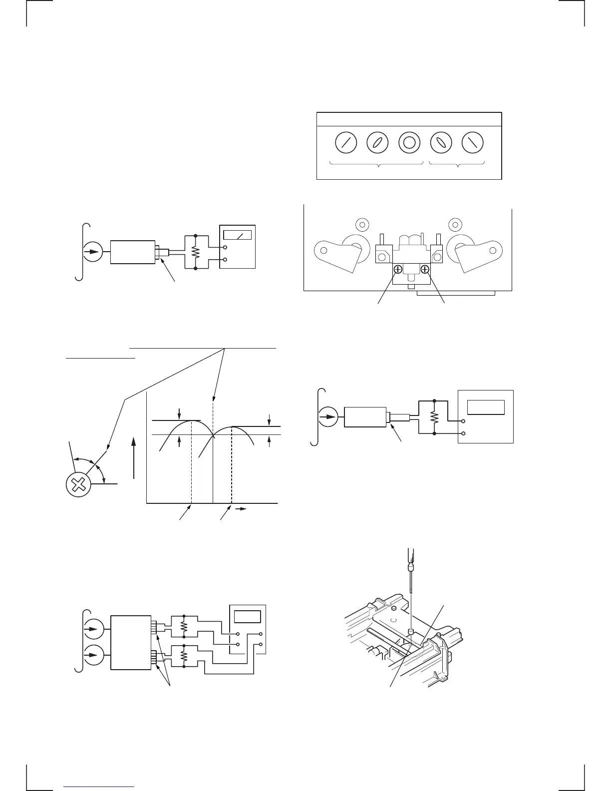
Tape Speed Adjustment
Procedure :
Mode : FWD playback
1. Enter the FWD playback mode, and play back test tape.
2. Adjust the adjustment control (variable resistor) of the motor
(M902) until the frequency counter reading becomes 3,000 Hz
± 90 Hz.
3. Confirm that the tape speed deviation between tape top and tape
end is within 3%.
Adjustment location :
test tape
P-4-A100
(10kHz, –10dB)
set
LINE OUT
47k
Ω
level mete
Record/Playback Head Azimuth Adjustment
Note: • Perform this adjustment after the head is turned around.
(If the head is positioned in the FWD direction, turn around
the head and start adjustment from the REV mode as
described below.)
* When the azimuth adjustment is performed, the azimuth
adjustment screw must end up with rotation of tightening
direction (i.e. clockwise direction).
Adjustment procedure :
1. Mode: REV playback
2. Turn the azimuth adjustment screw for the maximum output
level of L-CH and R-CH.
If the peak levels do not match for L-CH and R-CH, turn the
adjustment screw until both of output levels match together
within 1 dB of peak.
3. Phase Check
Mode: REV playback
test tape
P-4-A100
(10kHz, –10dB)
L-CH
R-CH
set
47k
Ω
47k
Ω
oscilloscope
LINE OUT
V H
Oscilloscope Lissajous waveform
in phase 45
°
90
°
180
°
135
°
Good Wrong
Adjustment screw (FWD side) Adjustment screw (REV side