TC-SD1
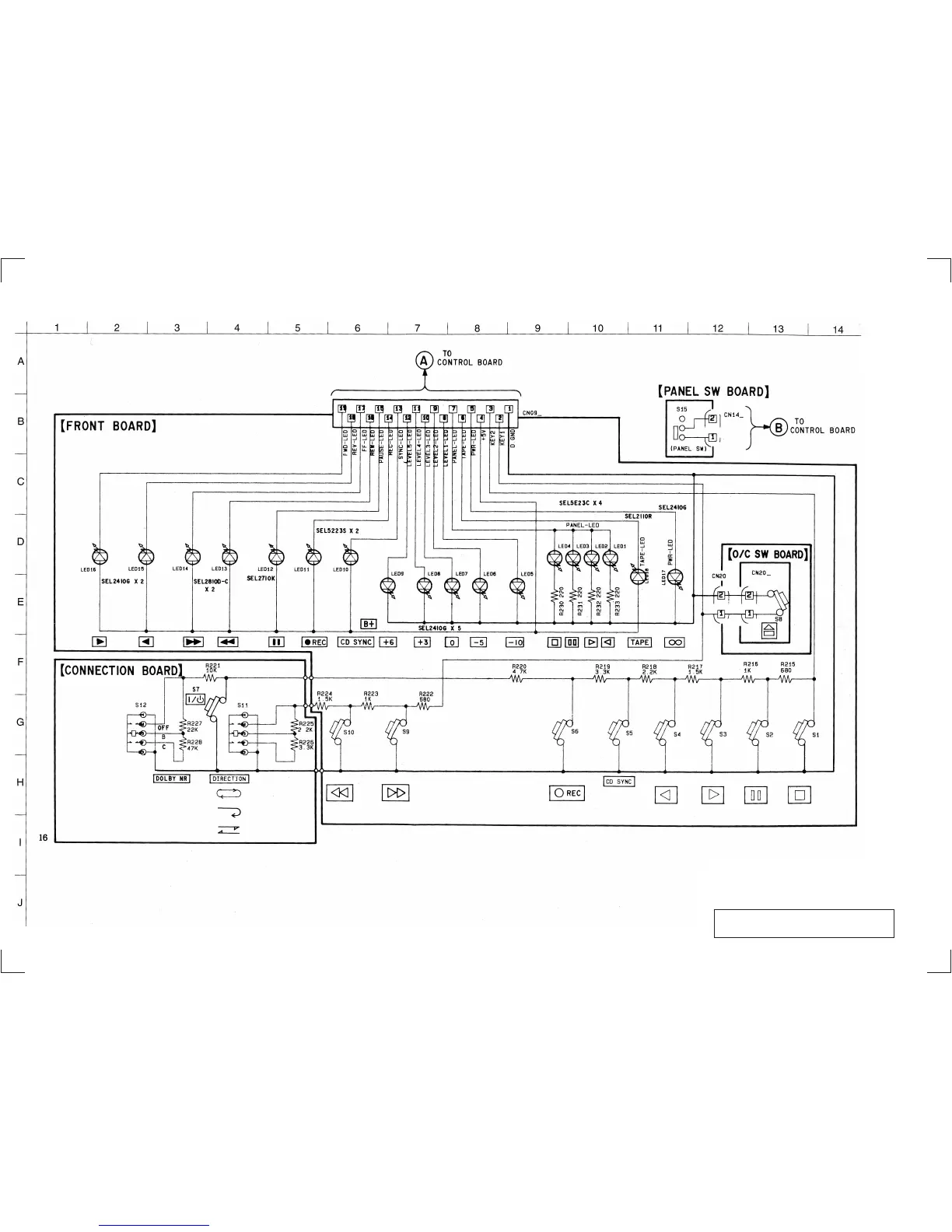
3-2. SCHEMATIC DIAGRAM — DISPLAY SECTION —
— 9 — — 10 —
Note on Schematic Diagram:
• All resistors are in Ω and
1
/
4
W or less unless otherwise
specified.
• C : panel designation.
• U : B+ Line.
Note: The components identified by mark ! or dotted line
with mark ! are critical for safety.
Replace only with part number specified.