GDM-200PS/200PST/200PST9
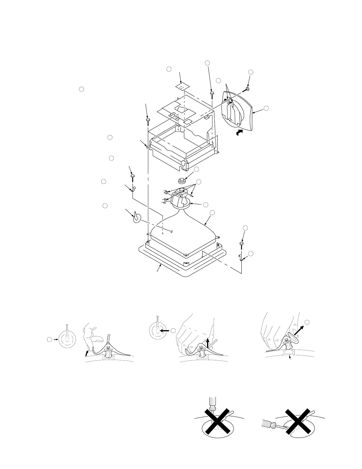
2-6. PICTURE TUBE REMOVAL
3 When one side of the rubber cap is
separated from the anode button, the
anode-cap can be removed by turning
up the rubber cap and pulling up it in the
direction of the arrow c.
• HOW TO HANDLE AN ANODE-CAP
1
Don’t hurt the surface of anode-caps with shartp shaped material!
2 Don’t press the rubber hardly not to hurt inside of anode-caps!
A material fitting called as shatter-hook terminal is built in the
rubber.
3 Don’t turn the foot of rubber over hardly!
The shatter-hook terminal will stick out or hurt the rubber.
a
b
c
Anode Button
• REMOVAL OF ANODE-CAP
NOTE: Short circuit the anode of the picture tube and the anode cap to the metal chassis, CRT shield or carbon painted on the CRT, after
removing the anode.
• REMOVING PROCEDURES
1
Turn up one side of the rubber cap in
the direction indicated by the arrow a.
2 Using a thumb pull up the rubber cap
firmly in the direction indicated by the
arrow b.
2-3
A board
10
Anode cap
8
Screw
(+P 4 x 12)
6
Screw
(+P 4 x 12)
4
Three connectors
(CN2, 4, GND)
9
Screw
(+BVTT 4 x 8)
1
CN4
CN2
GND
Stand assy
3
Hook (17)
5
Hook (17)
7
Two screws
(+BVTP 3 x 10)
11
Four screws
(Tapping screw 5 : U/C, SH model)
(Self tapping screw 5 : AEP, UK model)
12
Chassis assy
13
Picture tube
16
Cushion
Two claws
2
Deflection yoke
15
Neck assy
14