KD-27FS170/32FS170/36FS170
KD-27FS170/32FS170/36FS170
36
SECTION 4: CIRCUIT ADJUSTMENTS
Electrical Adjustments by Remote Commander
Use the Remote Commander
(RM-YD006) to perform the circuit adjustments in this section.
Test Equipment Required: 1. Pattern generator 2. Frequency counter 3. Digital multimeter 4. Audio oscillator
4-2. ACCESSING THE SERVICE
ADJUSTMENT MODE
1. Standby mode (Power off).
2. Press the following buttons on the remote commander within a
second of each other:
DISPLAY
Channel
5
Sound Volume
+
POWER
The screen displays the fi rst service data category item.
Category
Display
Item
Display
Data
Signal
Type
Channel
Type
NTSC VIDEO1DEF
M65586MK-056FP D1.0
HSIZ 1:35 NVM:OK
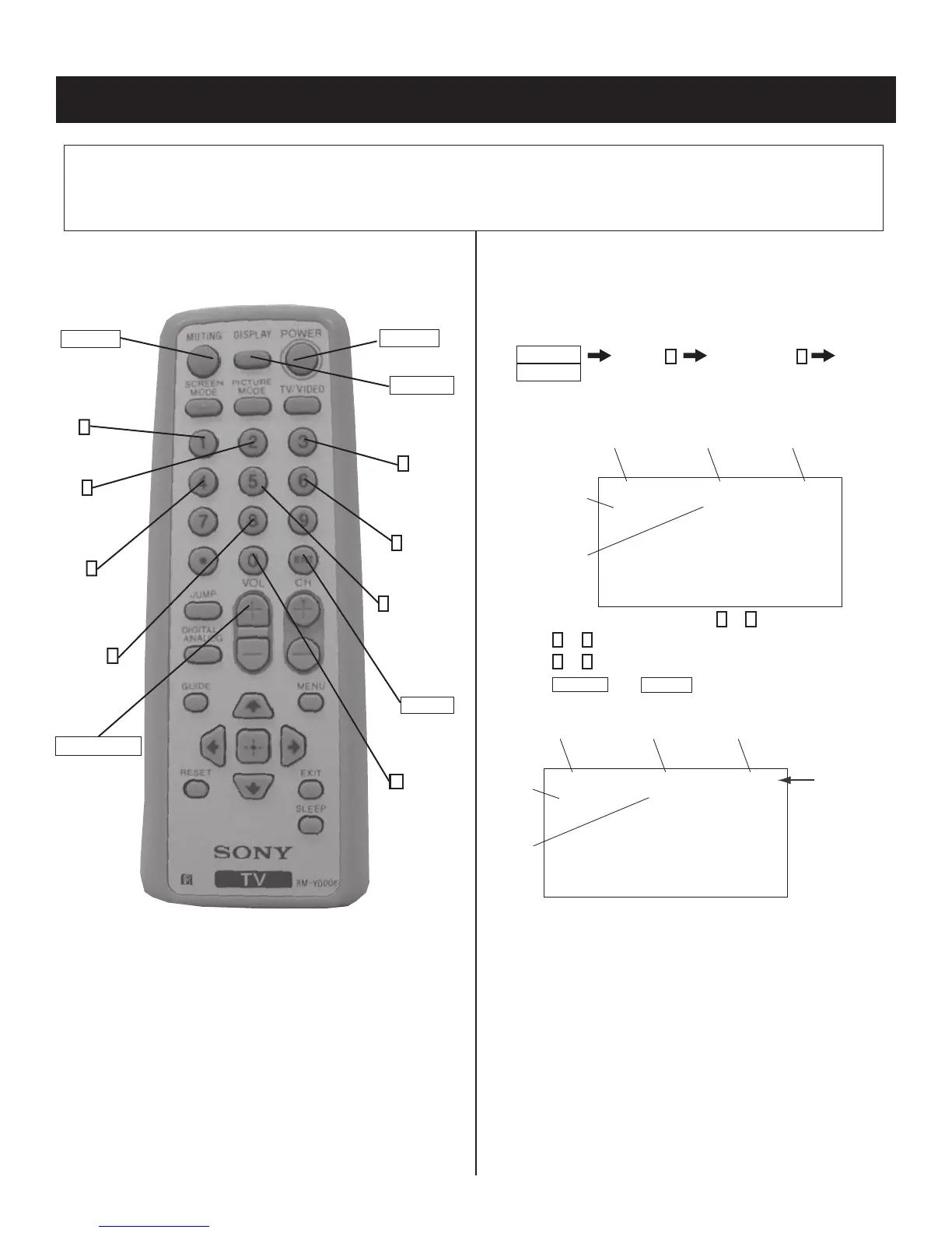
1. On the Remote Commander press
2
or
5
to select the category.
2. Press
1
or
4
to select the item.
3. Press
3
or
6
to change the data value.
4. Press
MUTING
then
ENTER
to write into memory.
Category
Display
Item
Display
Data
Signal
Type
Channel
Type
NTSC WRITEDEF
M65586MK-056FP D1.0
HSIZ 1:35 NVM:OK
Text
changes to
“WRITE” and
changes
colors from
green to red
DISPLAY
(Service Mode)
0
(Remove from
memory)
POWER
RM-YD006
(Service Mode)
MUTING
(Enter into
memory)
4
Display previous
Item
1
Display next
Item
2
Display next
Category
4-1. REMOTE ADJUSTMENT BUTTONS AND
INDICATORS
8
(Initialize)
3
Increase
Data value
6
Decrease
Data value
5
Display previous
Category
ENTER
(Enter into
memory)
VOLUME (+)
(Service Mode)
 Loading...