KD-27FS170/32FS170/36FS170
KD-27FS170/32FS170/36FS170
38
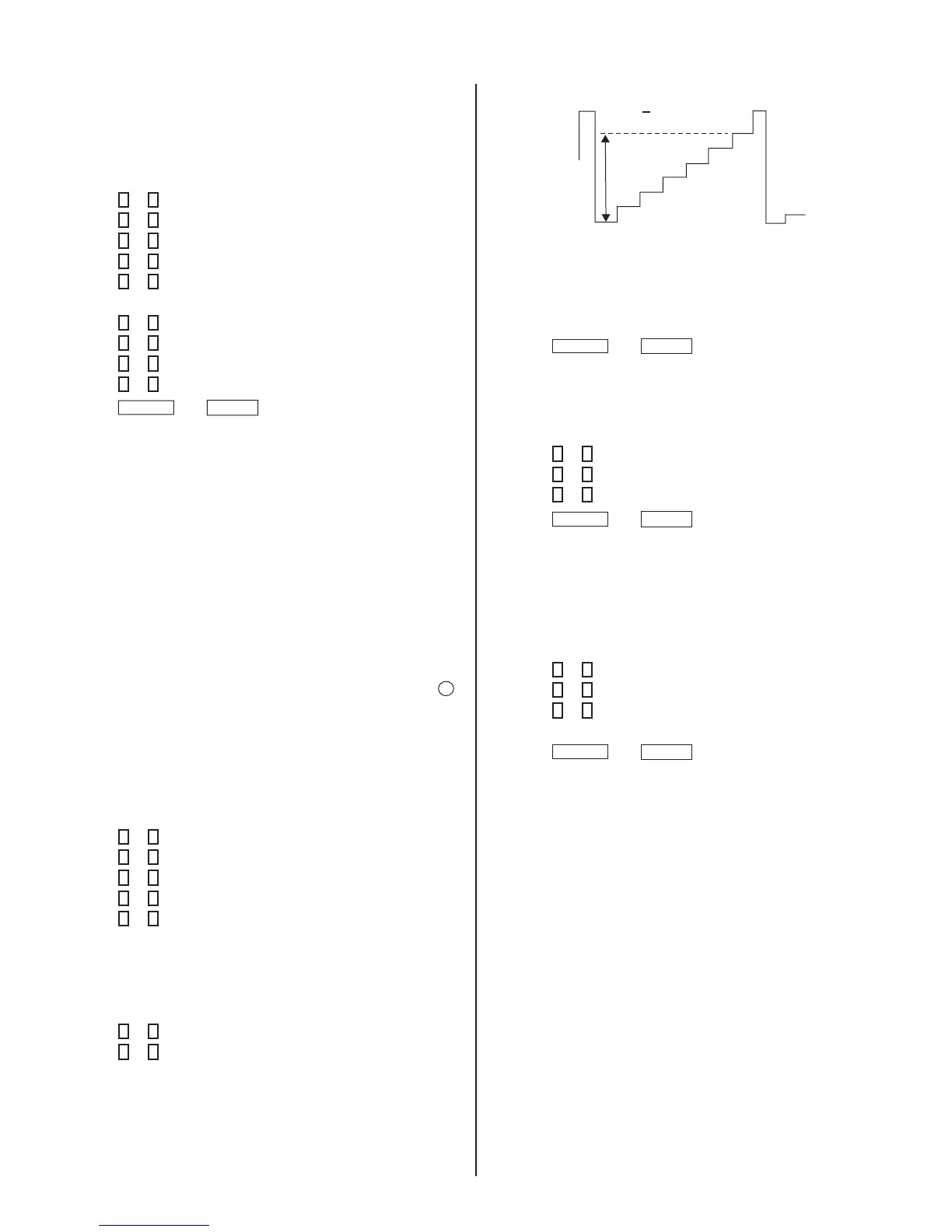
80 + 2Vpp
12. Repeat steps 5 thru 8 to reset GON and BON values to “1”.
R ON: ON (1)
G ON: ON (1)
B ON: ON (1)
13. Press
MUTING
then
ENTER
to write into memory.
Display Position Adjustment (DISP)
1. Input a color-bar signal.
2. Access Service Adjustment Mode.
3. Press
2
or
5
to select the Microprocessor category.
4. Press
1
or
4
to display the DISP item.
5. Press
3
or
6
to adjust characters to the center.
6. Press
MUTING
then
ENTER
to write into memory.
7. Check to see if the text is displayed on the screen.
Sub Bright Adjustment (SBRT)
1. Input a monoscope signal.
2. Access Service Adjustment Mode.
3. Set the PICTURE and BRIGHTNESS to minimum.
4. Press
2
or
5
to select the VP1 category.
5. Press
1
or
4
to display the SBRT item.
6. Press
3
or
6
to obtain a faintly visible 20 IRE mark, after that
increase +3 steps.
7. Press
MUTING
then
ENTER
to write into memory.
4-4. WHITE BALANCE ADJUSTMENTS
1. Input an entire white signal with burst.
2. Access Service Adjustment Mode.
3. Set the PICTURE and BRIGHTNESS to minimum.
4. Adjust with SBRT if necessary.
5. Press
2
or
5
to select the VP1 category.
6. Press
1
or
4
to display the GCUT item.
7. Press
3
or
6
to adjust for the best white balance.
8. Press
1
or
4
to display the BCUT item.
9. Press
3
or
6
to adjust for the best white balance.
10. Set the PICTURE and BRIGHTNESS to maximum.
11. Press
1
or
4
to display the GDRV item.
12. Press
3
or
6
to adjust for the best white balance.
13. Press
1
or
4
to display the BDRV item.
14. Press
3
or
6
to adjust for the best white balance.
15. Press
MUTING
then
ENTER
to save into the memory.
4-5. A BOARD ADJUSTMENTS
H. Frequency (Free Run) Check
1. Input a TV mode (RF) with no signal.
2. Connect a frequency counter to base of Q501
(TP-25 H. DRIVE) on the A Board.
3. Check H. Frequency for 15735 ± 200 Hz.
V. Frequency (Free Run) Check
1. Select video 1 with no signal input.
2. Set the conditions for a standard setting.
3. Connect the frequency counter to TP-27 (V OUT) or CN501 pin
6
(V DY+) and ground on the A Board .
4. Check that V. Frequency shows 60 ± 4 Hz.
Drive (SCON)
1. Input a color-bar signal and set the level to 75%.
2. Set in Pro mode + PICTURE MAX.
3. Access Service Adjustment Mode.
4. Press
2
or
5
to select the VP1 category.
5. Press
1
or
4
to display the GON item.
6. Press
3
or
6
to adjust to 0.
7. Press
1
or
4
to display the BON item.
8. Press
3
or
6
to adjust to 0.
Note: Leave RON set to “1”.
R ON: ON (1)
G ON: OFF (0)
B ON: OFF (0)
9. Connect an oscilloscope probe to C Board, CN705 pin3 (KR).
10. Press
1
or
4
to display the SCON item.
11. Press
3
or
6
to adjust the value of SCON to 80 ± 2Vpp.



 To Next Page