SONY.:
SERVICE
MANUAL
US Model
Canadian Model
Chassis
No.
SCC-AOBA-A
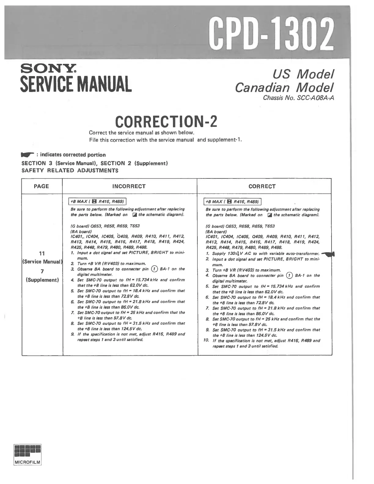
CORRECTION-2
Correct
the
service manual
as
shown below.
File
this correction with
the
service manual and supplement-1 .
..-
: indicates
corrected
portion
SECTION 3 (Service Manual), SECTION 2 (Supplement)
SAFETY
RELATED ADJUSTMENTS
PAGE
11
(Service Manual
7
(Supplement)
INCORRECT
I +B
MAX
( H R476. R4BS) I
Btl sure to
perform
the
following
adjustment
aftllr
replacing
tile
PIIrtI
below. (Marked on
~
the schematic diagram).
(G board)
0653.
R658. R659. T653
(BA
bOllrd)
IC407
•.
IC404. IC405.
(240S.
R40S. R470. R417. R472.
R473. R474. R475. R476. R477. R478.
R47S. R424.
R425. R44B.
R47S.
R4BO.
R4BS.
R488.
7.
Input
a
dot
signal
and
Slit PICTURE.
8RIGHT
to
mini·
mum.
2.
Turn +B VR
(RV403)
to
maximum.
3.
Ob$llTVe
BA board
to
connectllr
pin
(])
8A·
7
on
the
digitsl
multimeter.
4.
Slit
SMC'70
output
to
fH
a 75.734
kHz
and
confirm
that
the
+8
linll
isle$$ than
62.0V
dc.
5.
Slit
SMC·70
output
to
fH - 78.4
kHz
and
confirm
that
the
+8
line
is
le$$
than 72.8 V
dc.
6.
Sat SMC'70
output
to
fH
- 27.8
kHz
and
confirm
that
thll +8 linll
is
111$$
than
86.0V
dc.
7.
Set SMC·70
output
to
fH
-
25
kHz
and
confirm
that
the
+B /ine
is
le$$
than
S7.8V
dc.
8.
Set SMC·70
output
to
fH;'
37.5
kHz
and
confirm
that
the
+8
line
is
less
than 7
24.5V
dc.
S.
If
the specification is
not
met. adjust R476. R4BS
and
reptlBt steps 7
and
3
until
satisfied.
CORRECT
I +B
MAX
( H R476. R4BS) I
811
surll
to
perform
the
following
adjustment
after
replacing
tIIlI PIIrts below. (Marked
on
~
the schematic diagram).
(G
board)
0653.
R658. R65S. T653
(8A
board)
IC407. IC404. IC405. 040S. R40S. R470.
R477. R472.
R473. R474. R475. R476. R477. R478.
R47S. R424.
R425. R44B.
R47S.
R4BO.
R4BS.
R4B8.
7.
Supply 730±i V
AC
to
with
variabla auto·transformer.
-..11
2.
Input
a
dot
signal
and
sat PICTURE.
8RIGHT
to
mini'
mum.
3.
Turn
+8
VR (RV403)
to
maximum.
4.
ObseTVII
8A
board
to
connectsr
pin
(])
BA·
7 on the
digitsl
multimllter.
5.
Slit
SMC'70
output
to
fH
- 75.734
kHz
and
confirm
that
the
+8
linll isle$$ than
62.0V
dc.
6.
Set SMC'70
output
to
fH
= 78.4
kHz
and
confirm
that
the
+8
line
is
IIIss
than
72.8V
dc.
7.
Set SMC·70
output
to
fH
- 27.8
kHz
and
confirm
that
the
+8
line
is
less
than
86.0V
dc.
8.
Set SMC'70
output
to
fH
z
25
kHz
and
confirm
that
the
+8
line
is
less
than
S7.8V
dc.
S.
Set SMC·70
output
to
fH
- 37.5
kHz
and
confirm
that
tha
+8
line
is
less
than 724.5V dc.
70.
If
the·specification
is
not
met. adjust R476. R4BS
and
repfJllt steps 7
and
3
until
satisfied.