PAGE
12
Service
Manual)
8
(Supplement)
INCORRECT
II
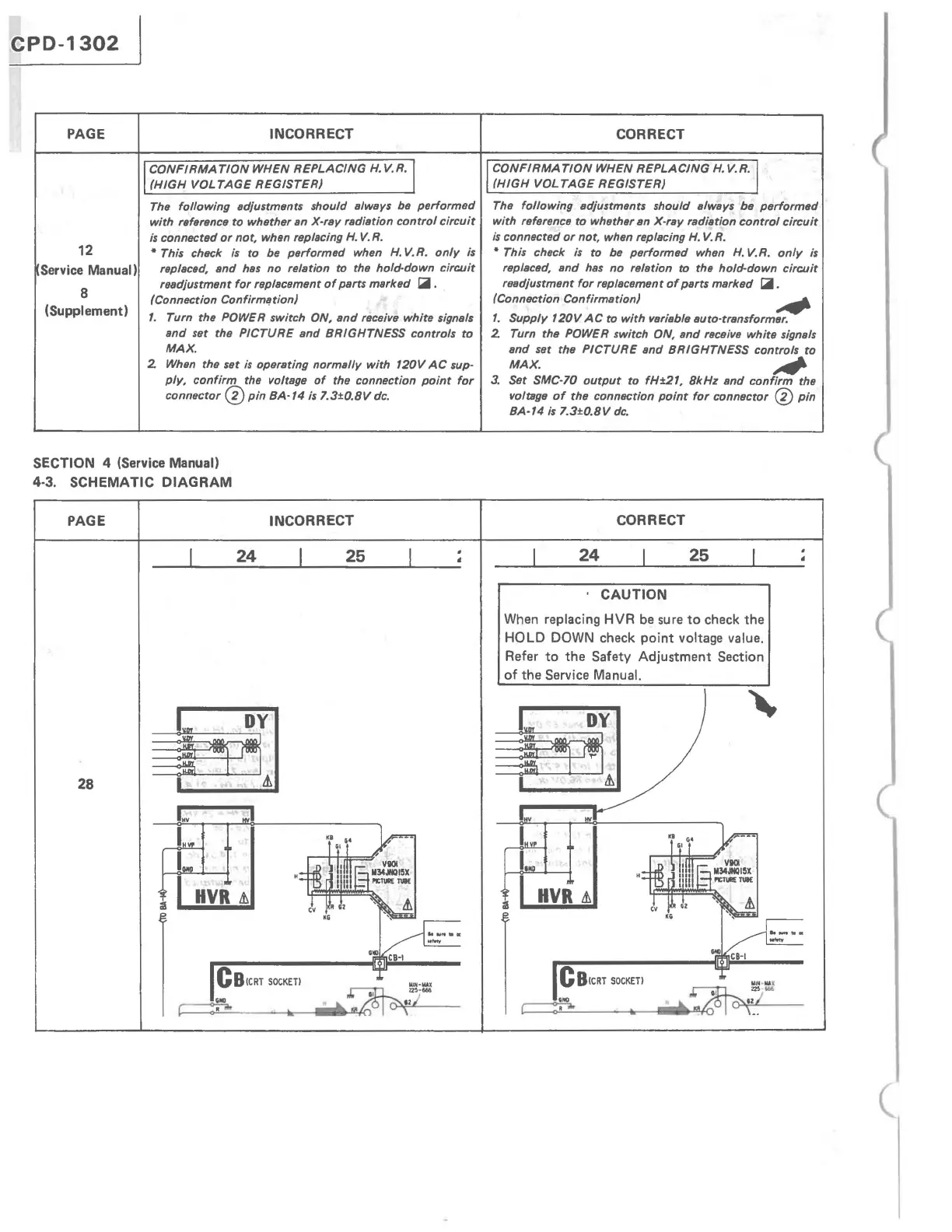
CONFIRMATION
WHEN REPLACING
H.
V.R./
II
(HIGH
VOLTAGE
REGISTER)
The
following
Bdjustments should
BlwBYs
be
performed
with
reference
to
whether
Bn
X·ray radiBtion
control
circuit
is
connscted
or
not, when replBcing
H.
V.R.
• This chsck
is
to
be performed when
H.
V.R.
only
is
replBced, Bnd
hBS
no
relation to the hold·down
circuit
readjustment
for
replBcement
of
PBrtS
mBrked
~.
(Connsction Confirml!tion)
1.
Turn the POWER switch ON,
and
receive
white
signals
and
set the PICTURE Bnd BRIGHTNESS controls
to
MAX.
2.
When
the set
is
operBting normBlly
with
120V
AC
sup-
ply,
confirm
the voltBge
of
the connection
point
for
connector 0
pin
BA-14
is
7.3±O.BV
dc.
SECTION 4 (Service Manual)
4·3. SCHEMATIC
DIAGRAM
PAGE INCORRECT
24
25
28
I..
I
CB(CRT
SOCKET)
CORRECT
/
CONFIRMA
TlON
WHEN
REPLACING
H.
V.R./
(HIGH
VOL
TAGE
REGISTER)
The
following
Bdjustments should
BlwBYs
be
performed
with
reference
to
whether an X-ray rBdiBtion
control
circuit
is
connected
or
not, when replacing
H.
V.R.
• This check
is
to
be
performed
when
H.
V.R.
only
is
replaced, Bnd
hBs
no
relBtion to the hold-down
circuit
readjustment
for
replacement
of
pBrts marked
~.
(Connsction ConfirmBtion)
,.
1.
Supply
120V
AC
to
with
variBble Buto·transformer.
2.
Turn the POWER switch ON, Bnd receive
white
signels
Bnd set the
PICTURE
Bnd BRIGHTNESS controls
to
MAX.
~
3.
Set SMC-70
output
to
fH±21, BkHz
and
confirm
the
voltage
of
the connsction
point
for
connector ®
pin
BA·14
is
7.
3±O.BV
dc.
CORRECT
24
25
CAUTION
When replacing HVR be sure
to
check
the
HOLD DOWN check
point
voltage value.
Refer
to
the
Safety
Adjustment
Section
of
the
Service Manual.
CB(CRT
SOCKET)
(