– 23 –
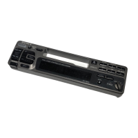
• MAIN BOARD IC501 µPD78058GC-462-3B9 (SYSTEM CONTROLLER)
Pin No. Pin Name I/O Function
1 RC-IN0 I Rotary remote commander shift key A/D input terminal
2 ILL-IN I Dimmer detection signal input Dimmer is present at input of “L”
3 NIL I Not used (fixed at “L”)
4 AVSS — Ground terminal (for A/D converter)
5 LCDANG O Output signal for the LCD view angle adjustment
6 NIL I Not used (fixed at “L”)
7 AVREF1 I Reference voltage (+5V) input terminal (for D/A converter)
8 RE IN0 I Rotary encoder (RE701) input terminal
9 RE IN1 I Rotary encoder (RE701) input terminal
10 SUB-F O Sub-woofer control signal output terminal Not used (pull down)
11 COLSEL I
Input terminal to set whether the illumination color change function is present or not
“L”: illumination color change function is present (fixed at “L” in this set)
12 LCDSO O Serial data output to the liquid crystal display driver (IC701)
13 LCDCKO O Serial data transfer clock signal output to the liquid crystal display driver (IC701)
14 LCDCE O Chip enable output to the liquid crystal display driver (IC701)
15 LCDINH O
Blank indicate control signal output to the liquid crystal display driver (IC701)
“L”: no display
16 UNISI I Serial data input from the SONY bus interface (IC571)
17 UNISO O Serial data output to the SONY bus interface (IC571)
18 UNICKI I Serial data reading clock signal input terminal (for SONY bus)
19 UNICKO O
Serial data transfer clock signal output to the tuner/tape deck system controller (IC101) and
SONY bus interface (IC571)
20 BUSON O
Bus on/off control signal output to the tuner/tape deck system controller (IC101) and SONY bus
interface (IC571) “L”: bus on
21 SYSRST O
Reset signal output to the tuner/tape deck system controller (IC101) and SONY bus interface
(IC571) “L”: reset
22 AMPON O Standby control signal output to the power amplifier (IC701) “L”: standby
23, 24 NCO O Not used (open)
25 PW-ON O Main system power supply on/off control signal output to the BA3918 (IC601) “H”: power on
26 ILL-ON O
27 COLOR O Illumination color selection signal output “H”: amber, “L”: green
28 NCO O Not used (open)
29 to 32 NIL I Not used (fixed at “L”)
33 GND — Ground terminal
34, 35 NIL I Not used (fixed at “L”)
36 to 39 NCO O Not used (open)
40 AD-ON O Power supply on/off control signal output for the A/D converter “L”: power on
41 NCO O Not used (open)
42 PW-SEL I
Power select switch (S501) input terminal
“L”: position A or off (halt mode), “H”: position B or on (operation mode)
43 RC-IN1 I Rotary remote commander shift key A/D input terminal
44 TEST I Setting terminal for the test mode “L”: test mode (normally fixed at “H”)
45 EQ-SEL I Equalizer selection input terminal (fixed at “H”)
46 BEEP O Beep sound drive signal output terminal
Power supply on/off control signal output terminal at the illumination and liquid crystal display
driver (IC701) “H”: power on
At power select switch (S501) on mode: “H” output at the accessory on
At power select switch (S501) off mode: “H” output at the power on
 Loading...