This document provides operating instructions for the Sophos SG 430/450 Rev. 2 appliances, which are designed for network security in commercial, industrial, and residential environments. The manual covers installation, configuration, and maintenance, emphasizing safe and proper operation.
Function Description
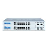
The Sophos SG 430/450 appliances are hardware devices developed for use in networks, serving as security appliances. They are designed to operate as standalone units, providing robust cybersecurity. The SG 450 model, in particular, includes a redundant power supply system to enhance availability, allowing for the easy and quick exchange of defective power supply units during operation. This model is also equipped with a RAID system with two hard disks to improve transfer rates, data security, and overall availability. The appliances support various network modules, including SFP (1 GbE) or SFP+ (1/10GbE) GBIC Ports, which convert electronic signals into optical signals for flexible network connectivity. These ports utilize lasers to transmit signals over fiber optic cables, compliant with Class 1 Laser equipment requirements.
Usage Features
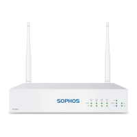
The SG 430/450 appliances feature a multi-function LCD display and an operating unit with four membrane keys for navigation and control. The LCD can display 16 characters per line and cycles through four views providing information on hardware status and specific system states, such as Sophos UTM version, appliance uptime, CPU load, memory usage, and traffic on interfaces.
The front panel includes various fixed GbE copper ports, some with bypass pairs, as well as fixed GbE SFP+ ports and expansion bays for optional Flexi Port modules. Connectivity options also include Micro USB, HDMI, and USB 3.0 ports. For management, there's an IPMI MGMT port and a COM (RJ45) port.
The devices offer several executable actions through the LCD and control keys:
- Change IP Address: Users can modify the IP address and netmask of available and enabled interfaces.
- Reboot Machine: This action performs a complete system shutdown and reboot.
- Shut Down: Allows for a clean shutdown of the system, stopping all running services.
- Factory Reset: Resets all configuration settings and options to their original state, deleting all user-entered data, including HTTP proxy cache, email queue, accounting and reporting data, passwords, and uninstalled updates. The software version, however, remains unchanged.
- Disable OTP (One Time Password) authentication: This feature allows disabling OTP authentication for selected webadmin and shell access options.
LED indicators provide visual feedback on the appliance's status:
- Power (LED Display): Green for active power supply, red for power supply failure, and blue for active SSD.
- RJ45 Ethernet Connector LEDs (ACT/LNK and Speed): The left LED (ACT/LNK) is green and indicates power reception and a good connection when constantly on. Flashing signifies network data transmission. If off, it indicates no power, no connection, or driver issues. The right LED (Speed) indicates connection speed: amber for 1,000 Mbps, green for 100 Mbps, and off for 10 Mbps.
- SFP+ Connector LEDs (ACT/LNK and Speed): Similar to RJ45, the left LED (ACT/LNK) indicates power and connection status (green constantly for active, flashing for data transmission, off for no power/connection/drivers). The right LED (Speed) indicates SFP+ connector speed: blue for 10,000 Mbps, amber for 1,000 Mbps, and off if not working or below 1,000 Mbps.
- LAN Bypass (LED Display): Green for active LAN Bypass, off for inactive.
The serial console provides an alternative access method for configuration and management. It can be connected via an RJ45 to DB9 adapter cable or a provided USB cable, with specific connection settings (38,400 bits per second, 8 data bits, no parity, 1 stop bit).
Maintenance Features
The manual emphasizes several maintenance and safety considerations:
- Battery Replacement: Caution is advised regarding the risk of explosion if the battery is replaced with an incorrect type. Used batteries must be disposed of according to instructions.
- Rack Mounting: Detailed instructions are provided for mounting the appliance in a rack, including using supplied screws, ensuring proper clearance for airflow and servicing, and securing front and rear brackets. It highlights the importance of using the correct screws to avoid damaging the hardware and invalidating the warranty.
- Redundant Power Supply (SG 450 only): The SG 450's redundant power supply system allows for easy and quick exchange of defective power supply units during operation. When a hardware defect occurs, LEDs turn red, and a continuous beeping sound alerts the user. The warning sound can be reset by pressing a red buzzer reset switch on the system chassis. Users are warned to remove the defective power unit from the power supply system before replacing it to prevent system failure and to wear protective gloves to avoid burns. Only power units purchased directly from Sophos or authorized partners should be used to maintain warranty validity.
- RAID Hard Disk System (SG 450 only): The SG 450's RAID system is monitored via the WebAdmin graphical user interface, with its status displayed on the dashboard. In case of a hard disk defect, a notification email is sent to the administrator, and the complete SG 450 unit needs to be exchanged.
- SFP GBIC Module Installation/Removal: Instructions are provided for carefully inserting SFP GBIC modules until they engage and for removing them by first detaching the fiberglass cable and then the module itself. Users are advised to consult the operation manual for the specific SFP GBIC module for detailed instructions on its release mechanism.
- CE and FCC Compliance: The appliances comply with FCC Class A, CE, C-Tick, VCCI, and UL standards. To maintain compliance, only CE and FCC compliant parts and proper cable and cabling techniques must be used.
- General Server Precautions: These include ensuring leveling jacks are extended, stabilizers are attached for single rack installations, racks are coupled for multiple installations, and the rack is stable before extending components. Only one component should be extended at a time to prevent instability. Users are advised to review electrical and general safety precautions, determine component placement before installing rails, install heaviest components at the bottom, allow hot-plug hard drives and power supply modules to cool before touching, and keep rack doors and panels closed for proper cooling.
- Rack Mounting Considerations: Important considerations include ambient operating temperature (ensuring compatibility with the manufacturer's maximum rated temperature), reduced airflow (mounting in a rack with sufficient airflow), mechanical loading (ensuring even loading to prevent hazardous conditions), circuit overloading (considering power supply circuitry and potential overcurrent issues), and reliable grounding (ensuring the rack itself is grounded and paying attention to power strip connections).