12
5. Connect the female connector block ‘s
clamp connections as described in the
terminal connection plans. When using
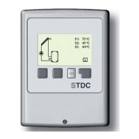
stranded cables, use a small screw driv-
er and push the orange buttons while
inserting (see fi g. C.2.1.c). When using
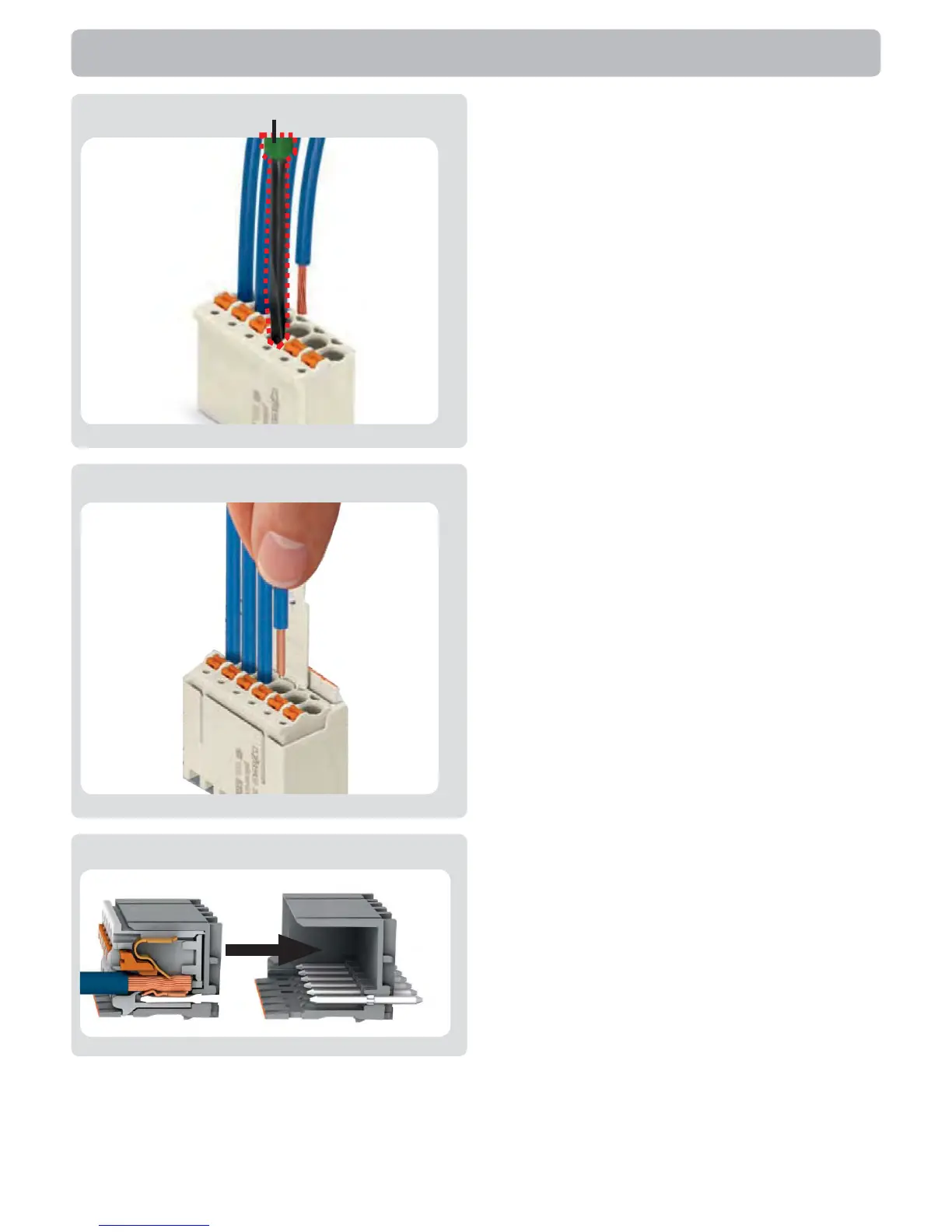
solid cable or end splice, just push the
cables in (see fi g. C.2.1.d).
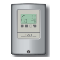
6. Plug Female connectors into onboard
headers.
7. Hinge the upper part of the casing on
the top of the lower part and close the
casing gently.
8. Fasten with screw.
9. Switch on mains voltage and place
controller in operation.
Installation
C.2.1.e
C.2.1.c
C.2.1.d
screw driver