20
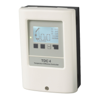
Brief description of switching function:
The ΔT function sensor 1 > sensor 2
switches the pump to relay R1.
The thermostat function via sensor 3
switches the pump to relay R2.
D.20 Universal ΔT controller
Installation
Low voltage max. 12VAC/DC connection
in the left-hand terminal compartment!
Terminal: Connection for:
S1 (2x) Sensor 1 (control)
S2 (2x) Sensor 2 (reference)
S3 (2x) Sensor 3 (thermostat)
The polarity of the sensors is freely se-
lectable.
Mains voltages 230VAC 50-60Hz Con-
nection in the right-hand terminal com-
partment!
Terminal: Connection for:
L Mains phase conductor L
N Mains neutral conductor N
R1 Pump L (speed)
N Pump N
R2 e.g. pump L
N e.g. pump N
The PE protective conductor must be
connected to the PE metal terminal block!
Sensor side
max. 12V
Caution
Mains side
230VAC
Danger
Caution
Relay R1: For speed control of
standard pumps, minimum load
20VA
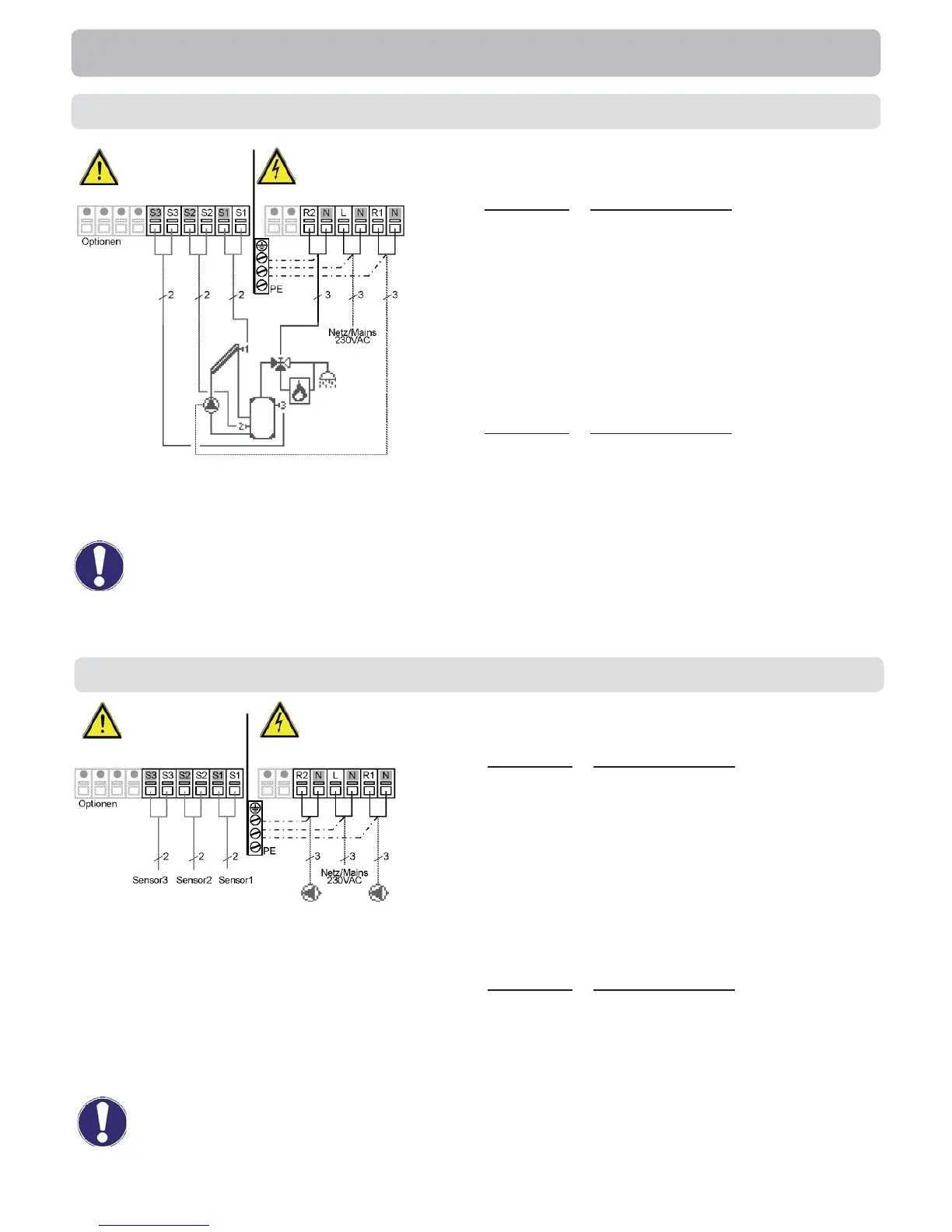
D.19 Solar + valve + thermostat
Low voltage max. 12VAC/DC connection
in the left-hand terminal compartment!
Terminal: Connection for:
S1 (2x) Sensor 1 collector
S2 (2x) Sensor 2 storage tank low
S3 (2x) Sensor 3 storage tank top
The polarity of the sensors is freely se-
lectable.
Mains voltages 230VAC 50-60Hz Con-
nection in the right-hand terminal com-
partment!
Terminal: Connection for:
L Mains phase conductor L
N Mains neutral conductor N
R1 Pump L (speed)
N Pump N
R2 Valve L
N Valve N
The PE protective conductor must be
connected to the PE metal terminal block!
Sensor side
max. 12V
Caution
Mains side
230VAC
Danger
Caution
Relay R1: For speed control of
standard pumps, minimum load
20VA


 To Next Page