7
Description of controller
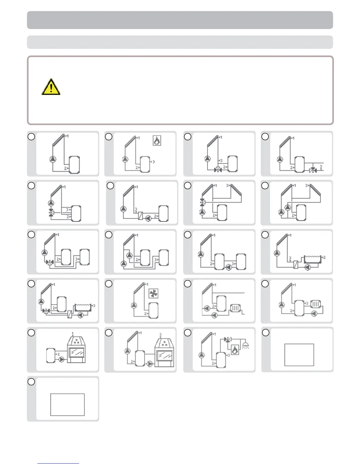
B.5 Hydraulic variants
Caution
The following illustrations should be viewed only as schematic dia-
grams showing the respective hydraulic systems, and do not claim to
be complete. The controller does not replace safety devices under any
circumstances. Depending on the specifi c application, additional system
components and safety components may be mandatory, such as check
valves, non-return valves, safety temperature limiters, scalding protec-
tors, etc., and must therefore be provided.
1
4
7
10
14
13
17
2
5
8
11
15
3
6
9
12
16
18 19
20
21
(T
(2xT
T
2xT