0
10 20 30 40 50 60
LoZ mV AnF M k
AUTO HOLD REL PEAK MAX MIN AVG
AC+DC
0
10 20 30 40 50 60
LoZ mV AnF M k
AUTO HOLD REL PEAK MA X MIN AVG
AC+DC
11
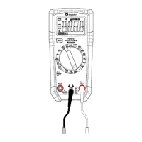
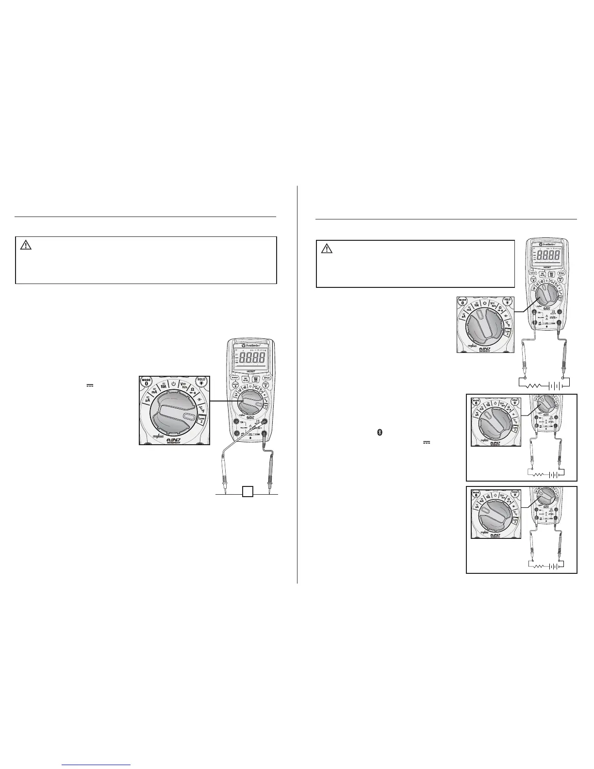
Operation cont.
1. Set the rotary function switch to
the Low Z position.
2. Press the MODE button to
select AC or DC voltage.
The AC “~” or DC “ ” symbol
will appear on the LCD display.
3. Insert the black test lead into
the COM input jack and the red
test lead into the V input jack.
4. Touch the test leads to the
circuit under test. If measuring
DC voltage, touch the red test
lead to the positive side of the
circuit and the black test lead
to the negative side of the circuit.
5. Read the voltage on the LCD display.
Low Z is used to check for “ghost” voltage. Ghost voltages are present when
non-powered wires are in close proximity to powered wires. Capacitive coupling
between wires make it appear that non-powered wires are connected to a real
source of voltage. The Low Z setting places a load on the circuit, which greatly
reduces the voltage reading when connected to ghost voltage.
Low Z AC/DC Voltage
Observe all safety precautions when working on live
voltages. Do not connect to circuits that exceed 600V when the meter is set
to Low Z. Do not use Low Z when testing circuits that could be harmed by
this function’s low input impedance.
WARNING:
V
-+
-+
-+
0
10 20 30 40 50 60
LoZ mV AnF M k
AUTO HOLD REL PEAK MAX MIN AVG
AC+DC
12
Operation cont.
1. Insert the black test lead into the
negative COM input jack.
2. For current measurements up to 10A,
set the rotary function switch to the
10A position and insert the red test
lead into the 10A input jack.
3. For current measurements up to
600mA, set the rotary function switch
to the mA position and insert the red
test lead into the µA mA input jack.
4. For current measurements up to 6000 µA,
set the rotary function switch to the µA
position and insert the red test lead into
the µA mA input jack.
5. Press the MODE button to select AC or
DC current. The AC “~” or DC “ ”
symbol will appear on the LCD display.
6. Remove power from the circuit under test,
then open up the circuit at the point where
you wish to measure current.
7. Touch the test lead probes in series with
the circuit being measured. For DC current,
touch the red probe to the positive side of
the circuit and touch the black probe to
the negative side of the circuit.
8. Apply power to the circuit.
9. Read the current on the LCD display.
AC/DC Current Measurements
MEASUREMENTS
UP TO 10A
Observe all safety precautions when
working on live circuits. Do not measure current on circuits
that exceed 1000V. Measurements in the 10A range should
be limited to 30 seconds maximum every 15 minutes.
WARNING:
MEASUREMENTS
UP TO 600mA
0
10 20 30 40 50 60
LoZ mV AnF M k
AUTO HOLD REL PEAK MAX MIN AVG
AC+DC
MEASUREMENTS
UP TO 6000 µA
0
10 20 30 40 50 60
LoZ mV AnF M k
AUTO HOLD REL PEAK MAX MIN AVG
AC+DC
0
10 20 30 40 50 60
LoZ mV AnF M k
AUTO HOLD REL PEAK MAX MIN AVG
AC+DC
0
10 20 30 40 50 60
LoZ mV AnF M k
AUTO HOLD REL PEAK MAX MIN AVG
AC+DC
0
10 20 30 40 50 60
LoZ mV AnF M k
AUTO HOLD REL PEAK MAX MIN AVG
AC+DC
 Loading...