0
10 20 30 40 50 60
LoZ mV AnF M k
AUTO HOLD REL PEAK MAX MIN AVG
AC+DC
0
10 20 30 40 50 60
LoZ mV AnF M k
AUTO HOLD REL PEAK MAX MIN AVG
AC+DC
13
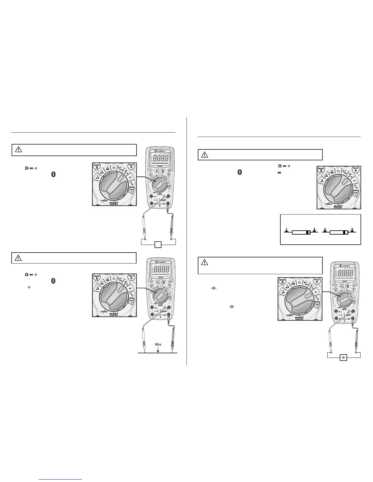
Operation cont.
1. Set the rotary function switch to
the position.
2. Press the MODE button until
the “ ” symbol appears on the
LCD display.
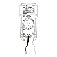
3. Insert the black test lead into the
COM input jack and the red test
lead into the Ω input jack.
4. Touch the test lead probes to the
device or wire under test.
5. A beeper will sound if the resistance is approximately
50Ω or less and the resistance value will be shown
on the LCD display.
Continuity
Never test continuity on a live circuit.
WARNING:
Ω
1. Set the rotary function switch to
the position
2. Press the MODE button until the
“Ω” symbol appears on the LCD
display.
3. Insert the black test lead into the
COM input jack and the red test
lead into the Ω input jack.
4. Touch the test lead probes to the component
under test. If the component is installed in a circuit,
it is best to disconnect one side before testing to
eliminate interference with other devices.
5. Read the resistance in on the LCD display.
Resistance Measurements
Never test resistance on a live circuit.
WARNING:
0
10 20 30 40 50 60
LoZ mV AnF M k
AUTO HOLD REL PEAK MAX MIN AVG
AC+DC
0
10 20 30 40 50 60
LoZ mV AnF M k
AUTO HOLD REL PEAK MAX MIN AVG
AC+DC
0
10 20 30 40 50 60
LoZ mV AnF M k
AUTO HOLD REL PEAK MAX MIN AVG
AC+DC
0
10 20 30 40 50 60
LoZ mV AnF M k
AUTO HOLD REL PEAK MAX MIN AVG
AC+DC
0
10 20 30 40 50 60
LoZ mV AnF M k
AUTO HOLD REL PEAK MAX MIN AVG
AC+DC
14
Operation cont.
1. Set the rotary function switch to
the position
2. Insert the black test lead into the
COM input jack and the red test
lead into the input jack.
3. Touch the test lead probes to
the capacitor under test.
4. Read the capacitance value on the
LCD display. It may take up to a
minute to get a stable reading on
large capacitors.
Capacitance Measurements
Safely discharge capacitors before
taking capacitance measurements.
WARNING:
1. Set the rotary function switch to the position.
2. Press the MODE button until the “ “ symbol
appears on the LCD display.
3. Insert the black test lead into the COM input jack and
the red test lead into the Ω input jack.
4. Touch the test lead probes to the diode under test.
5. Forward voltage will indicate
0.4 to 0.7 on the display. Reverse
voltage will indicate “OL”. Shorted
devices will indicate near 0 and
an open device will indicate “OL”
in both polarities.
Diode Test
Never test diodes in a live circuit.
WARNING:
Red Black Black Red
Probe Probe Probe Probe
Forward test Reverse test
 Loading...